Engine Design for Beginners:
The Dean 2.5cc Diesel
Last update: Feb, 2007
Click on photographs to view in more detail
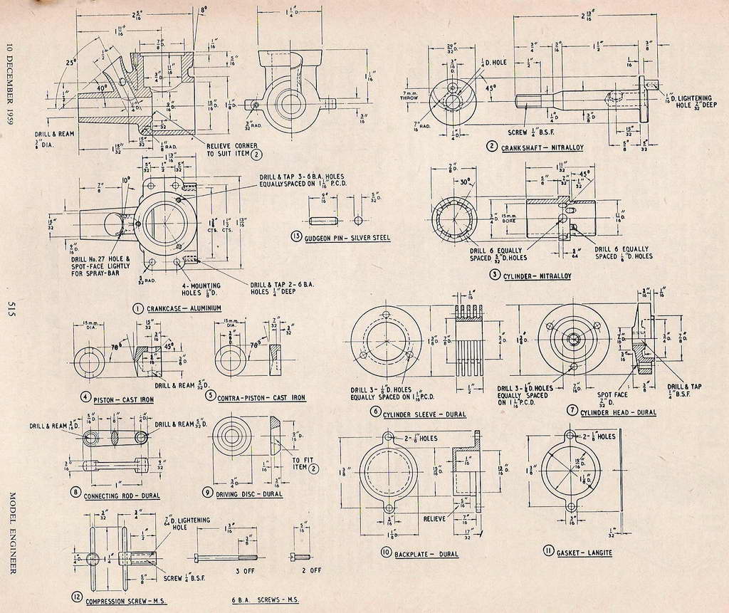
This engine was presented in an article by Mr RG Dean that appeared in The Model Engineer of December 10, 1959. Today, it seems to have effectively sunk without trace; the plan neither being available through the Model Engineer Plan Service, nor the X-List plans.
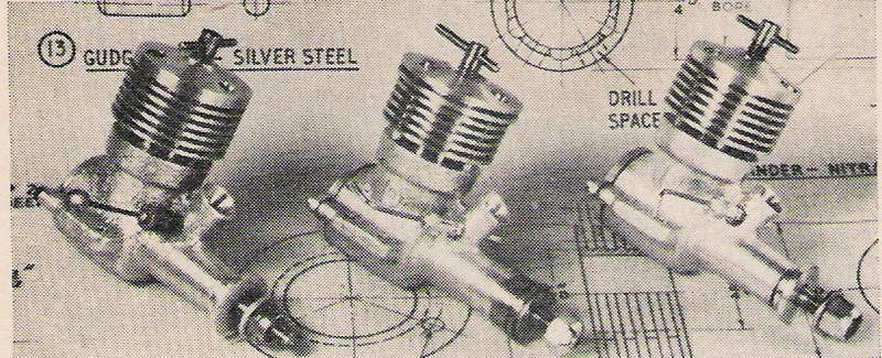
 Design wise, there are aspects of many English designs of the 50's in this engine. This is no bad thing. It is a modest, plain bearing (unbushed), front rotary valve (FRV) compression ignition engine with the very common 15mm bore and 14mm stroke formula for a displacement of 2.47cc. The simple cylinder liner utilizes a small adaptation of "Oliver porting" (see the Sugden Special Construction page for an explanation of this porting). As expected, the piston is from cast iron, with a conical crown.
Construction is based on a die cast crankcase and backplate which the designer produced using a plaster of paris molds (but not lost-wax, it seems). Unless precautions are taken, this can be extremely hazardous due to the danger of explosion from contact between molten metal and moisture present in the plaster. However if pre-cast components were readily availabile, the engine would be very suitable for first time engine builders. Without them, it moves into the advanced category where skills are required to either hog the case from the solid, or prepare dies and cast metal! Let's assume castings are available and see why the design is so good from a beginners' perspective:
- The size is just right; not too large, not too small.
- No screw-cutting required; all threads can be made with taps and die.
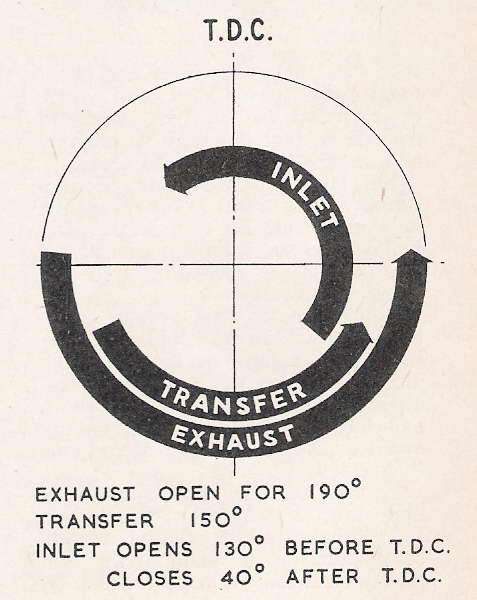
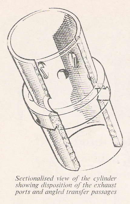
- No "special" cutters required. The exhaust ports are drilled, not slit as is normal for "Oliver" porting, so no slitting saw and arbour required.
- The shaft runs unbushed in the case, so the builder is not faced with machining press-fit tolerances, or messing with anaerobic adhesives.
- ED/DC transfer porting is used (an annular space around the lower projection of the cylinder), so no deep, close tolerance boring is required.
 There are downsides, naturally. Setup and workholding for the case will require precision and care. Drilling the ports will require a rotary table that can be angled for the transfers, although it would be possible to do this job using a block of hex steel to hold and index the cylinder, with a vertical slide fitted to the lathe cross-slide allowing the drill to be placed in the headstock for drilling the straight exhausts and the angled transfers. In fact, this set-up may even be easier than the rotary table approach.
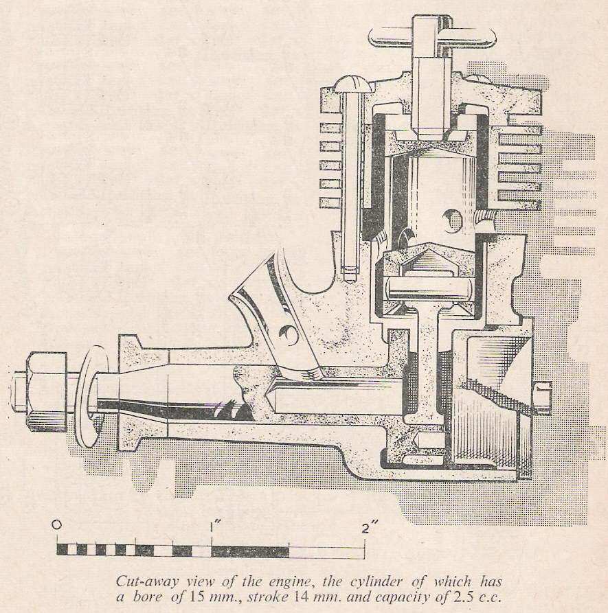
Notice that the primary compression seal is achieved on the underside of the cylinder liner exhaust belt only, under pressure exerted by the cooling jacket pressing on the top of the exhaust belt. The liner is kept centered in the transfer bore by a close fitting recess in the top of the crankcase. This is easy to machine. A fibre gasket could be fitted under the liner (much favoured by DC on their engines), but a well machined seat would suffice. I'd be tempted to make a one piece head, although the separate head simplifies machining the boss around the comp screw inside the cavity. This provides extra thread for the screw and could be moved to make it external.
Viewed as a first project engine, I really like this design. The only thing I'd change would be the induction. Converting it to rear rotary valve induction (RRV) would make it even simpler as there would be no critical port to drill precisely in the crankshaft, nor the corresponding angled venturi port. But this is a minor point. Mr Dean deserves credit for a well thought out, highly practical design, even if it does highlight the potential dependency between the availability of complex castings and ease of construction.
![]()
Back to the Model Engine News Home Page
Please submit all questions and comments to [email protected]