Cirrus Construction Log: Cylinder Studs
Created: September 2006
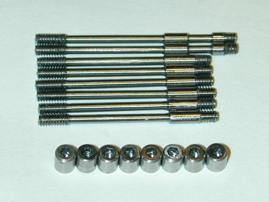
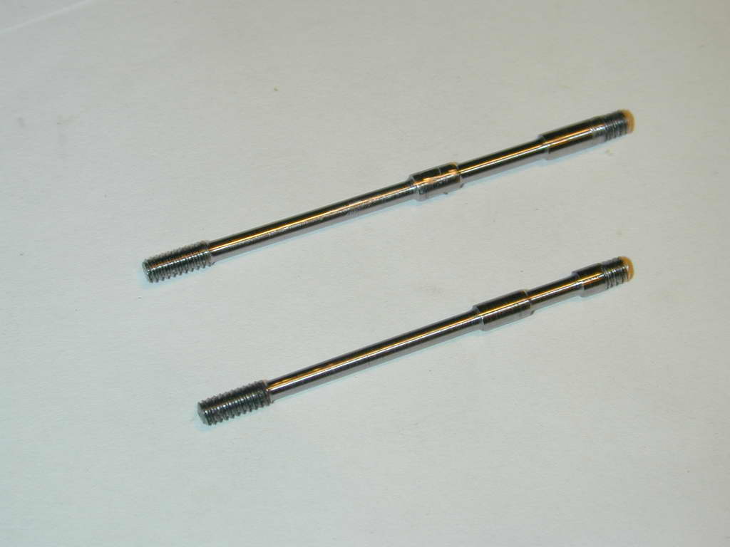
As drawn, the head hold-down bolts are machined from 3/16" (4.8mm) drill rod. Only the top 3/16" however stays at this diameter; most of the rest goes down to 2mm. After making a couple of these and finding it tedious and wasteful, I decided to try an experiment making one from a length of 3mm drill rod, threaded at both ends so it forms a for-real stud. A separate, custom made, Allen key nut completes the combo. This was successful and much simpler, so all the rest, plus replacements for the two already made were done this way.
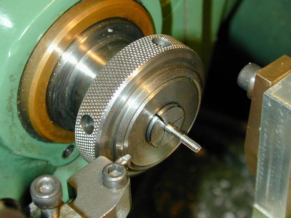 Photo 1 |
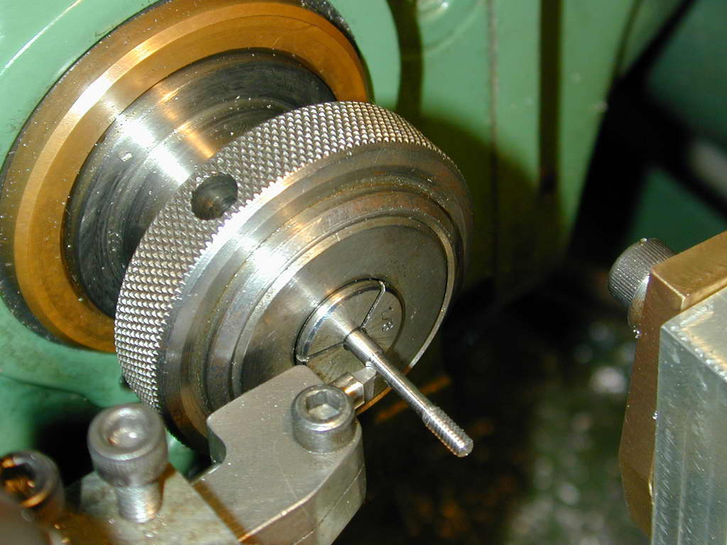 Photo 2 |
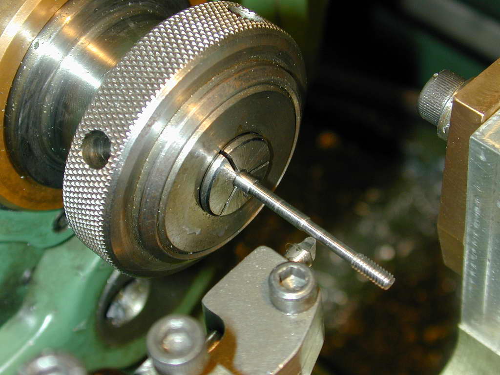 Photo 3 |
All work was done in a collet using the step-turning technique. In Photo #1, the bottom 1/4" has been reduced to 4-40 threading size and a short section above this reduced to finish size plus 0.002". The stock is then extended 1/2" and reduced to the same dimension (Photo #2). After another 1/2" extension and another step to make the overall necked down length 15/16", the hard part is complete (Photo #3). The top is reduced to 0.115", parted off, reversed, and threaded 4-40 for the nut. The finish and regularity from this process was quite good, but the "join" marks of the three steps were faintly visible, so a final pass to remove the last 2 thou was made.
 This cannot be done unsupported, so one of the special nuts is threaded onto the end of the stud to form a bearing for the travelling steady. The cut was applied by winding the top slide by hand so the steady remained "fixed". The finish looks a bit awful in the photos. Don't know why because to my eye, it looks rather good. Note the generous radius on the tool. This contours the ends, produces a better finish, and makes the tool edge last longer.
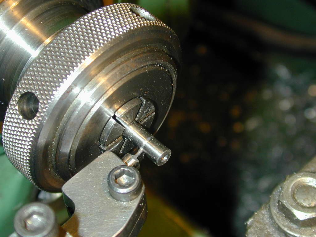 Photo 6 |
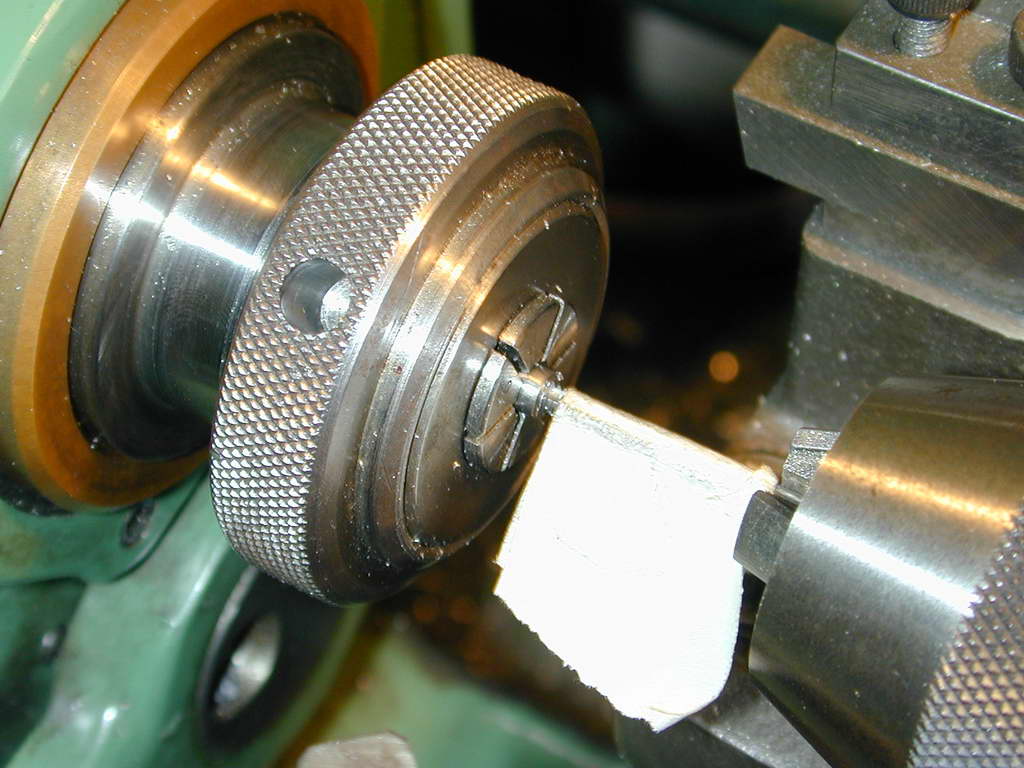 Photo 7 |
The "nuts" were drilled 4-40 tapping size and parted off at 0.200"; 0.012" longer than the 3/16" called for. They were then tapped from one end to produce about 0.1" of full thread, leaving another 0.1" for the broached hex socket. The tables say that about four threads are adequate for a 60° thread to develop its full shear strength, so any more is a waste. Photo #6 shows the blanks being parted off; #7 shows a piece of tape wrapped around the tap as a "depth stop". As we shall see, the #42 hole used as the tapping size provided a slightly undersize hole for the broach.
 After some almost but not quite successful experiments using the tailstock to ram a piece of Allen key into the nut as a broach, I hit on the sure-fire perfect solution. This involved a simple jig and some carefully applied brute-force. The photo shows front and back views of the tool and a finished, broached hex socket. A length of 4-40 threaded rod was gripped in the 3-jaw chuck and a nut blank threaded on with a brass washer underneath it until all was snug against the chuck jaws, leaving half the hole in the nut "free". The broach tool is drilled to a close sliding fit over the 3/16" diameter nut. It is drilled through for a close sliding fit for a length of Allen key stock. It's hard to see, but the cutting end of the broach has been lightly concaved by hand using a Dremel cut-off wheel to produce sharp edges with some rake.
Now, drum roll if you please maestro; gentlemen stand well back, and if ladies kindly remove their hats... The jig is slid over the nut and the protruding Allen key broach clouted earnestly with a carpenter's claw hammer! The jig aligns the broach over the hole and a couple of decent wacks are enough for it to bottom out on the threaded rod that has been adjusted to provide those four threads of engagement. All a bit violent and agricultural, but the socket is centered and clean! To be sure, the finished nuts were hardened and tempered.
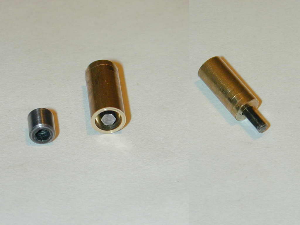
 Two of the ten studs pass through the inlet ports, so they need to be longer than the other eight and have a second reduced diameter neck where they occlude the port. This photo shows a stud made precisely to the dimensions given on the SIC plan (the long one), and one that actually fits correctly. As far as I know, this error was never mentioned as an errata, or "letter to the editor". Be warned: the SIC drawing for this part is just plain wrong! But for all that, the SIC drawings are at least complete; the Zimmerman plans don't show details of these at all. I used the wayward stud as the mandrel for the nut broaching exercise, so it was not a complete waste and I got to take out some frustration over the wasted time and material by wielding that claw hammer on it.


This page designed to look best when using anything but IE!
Please submit all questions and comments to
[email protected]
Copyright (c) Ronald A Chernich, 2004-2006. All rights reserved worldwide.