Cirrus Construction Log:
Inlet Manifold
Created: September 2006
At first glance, the inlet manifold comprises only five simple parts: two elbow tubes, two flanges, and a T shaped casting. But precise assembly of the manifold is a bit more critical than it seems at first glance.
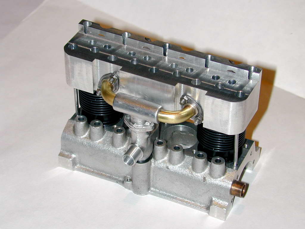 The one-piece head "floats"; that is, it is not keyed to the cylinders in any way. The top of the cylinders has been carefully milled to lie in the same plane. The head simply sits on the top of them and hopefully, the recesses in the heads align with the cylinder bores, both fore-aft and sideways. But the head is connected to the crankcase by the T shaped exhaust manifold, so unless this is precisely correct, it will tend to force the head out of alignment. Luckily we have some ways of adjusting the manifold components so they place the head in the correct alignment with the cylinders.
Flanges
 The attachment flanges are simple. I started by drilling a length of bar stock centrally for the tube, then offset appropriately for the attach hole which do not lie on a diameter. After turning a central boss and parting off the flange slices, the profile was marked out, the excess milled away, and the corners rounded with a fine file. It should be noted that the SIC drawing is probably in error in the position it shows for the mounting holes of the forward flange.
Elbows
The plans call for the elbow tubes to be bent from 1/4" OD copper pipe. I substituted brass as it was easily obtainable from the K&S rack at my local model store while I would have had to make my own copper pipe. In retrospect, copper would probably have been easier to form into the rather tight bend radius required.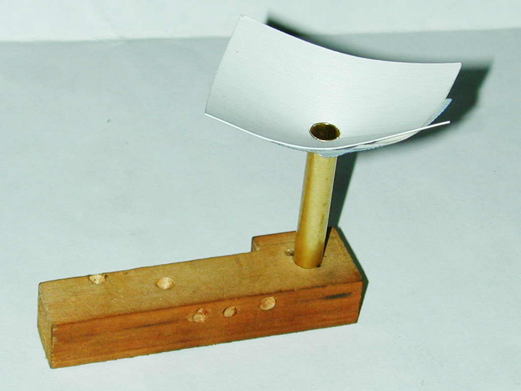 Experience forming the exhaust and inlet pipes for the "Morton M1" taught me that thin wall pipe needs to be fully annealed and filled with something if a crushed or "starved horse" look is to be avoided. This photo shows the annealed pipe resting in a close fitting blind hole in a wooden block with a paper funnel attached to the top. As the "Cerrobend" alloy used for packing melts at a temperature below that of boiling water (about 90&#`176;C), this is more than adequate for the job.
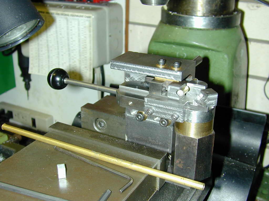 Photo 4 |
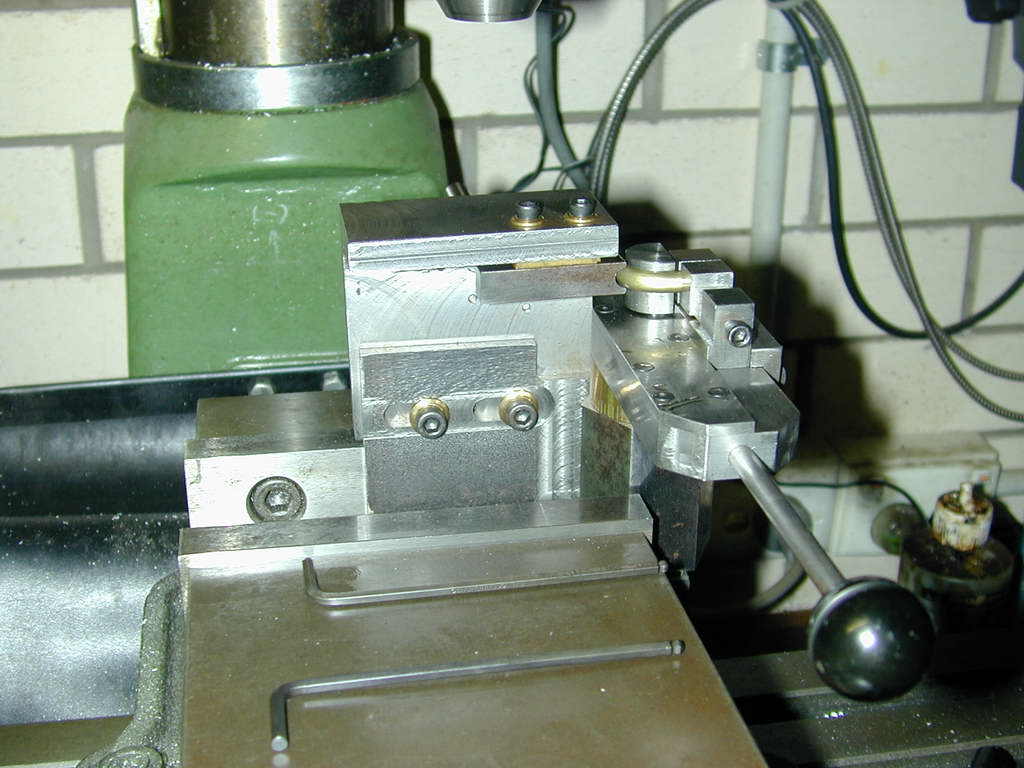 Photo 5 |
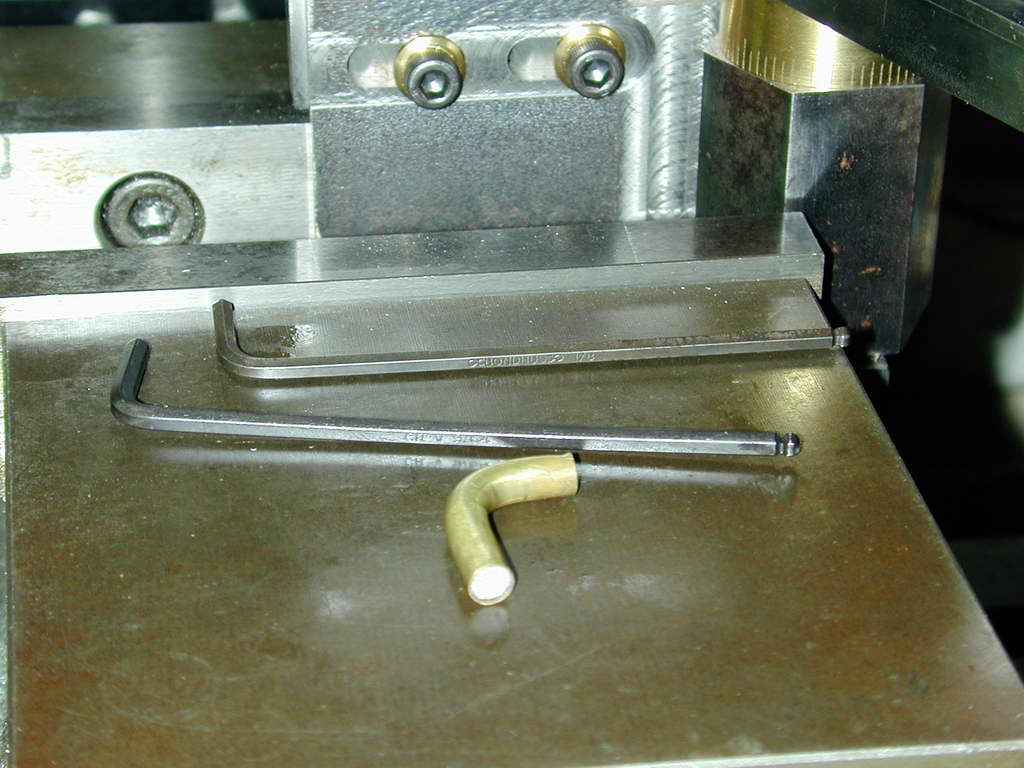 Photo 6 |
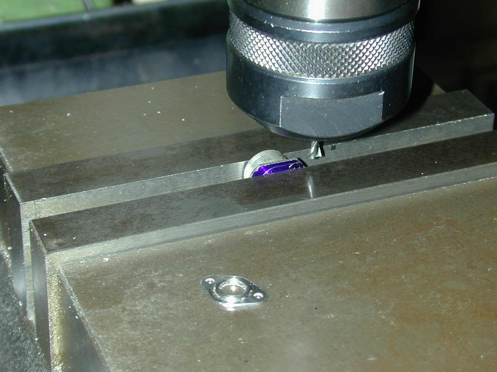
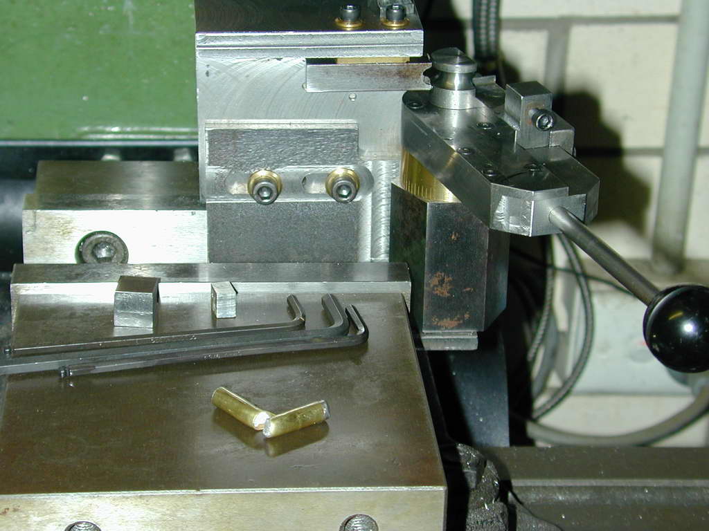
The Universal Pipe Bender made for the M1 job came out of wraps for the forming job. First, clamp blocks, forming die, and radius former had to be made for 1/4" pipe. This done, we see the filled pipe sitting between form and radius die, but not yet clamped in Photo 4. Photo 5 shows the bend formed. This requires significant force and a bit of over-cooking to allow for spring-back. The final result, prior to melting out the Cerrobend, appears in Photo 6.
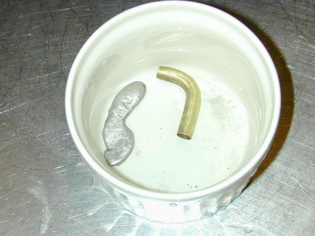 The Cerrobend "low temperature fixturing alloy" can be easily melted out by dropping the pipe into almost boiling water. The recovered blob is stored after cooling for re-use. Unlike the use of lead or tinman's solder as the filler, Cerrobend leaves the pipe clean of any material after removal.
 The pipes were pressed into the inlet holes with the flanges in place so that they line up with each other and align with the home in the upper crankcase where the cast T fitting will attach. The location of the flanges was then lightly scribed onto the tubes for silver-brazing.
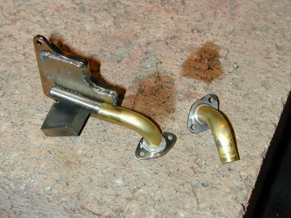 To hold the elbows and flanges for brazing, I've used a magnet plate salvaged from a dead hard disk drive. A piece of steel rod inside the tube holds the pipe and a block of steel acts as a foot to keep the flange horizontal. This photo shows one flange brazed up and the other fluxed up and aligned ready for the propane flame.
T-piece
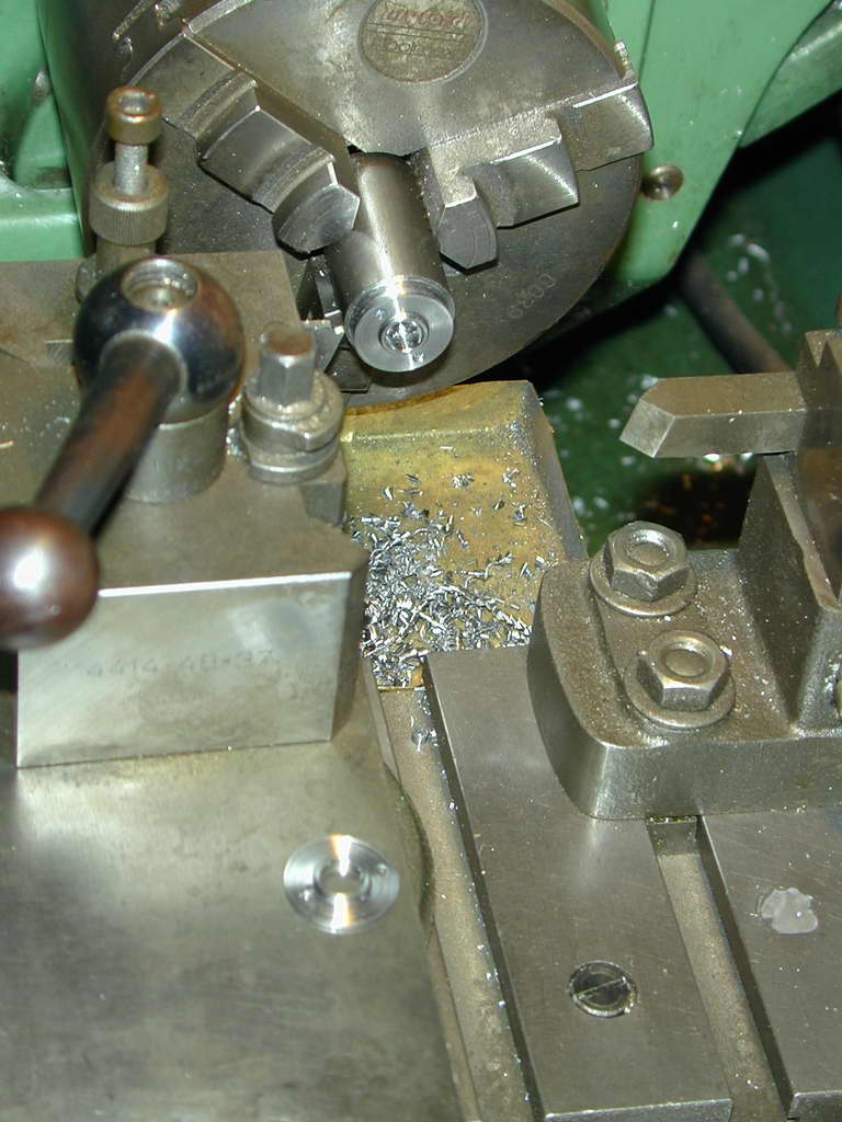
After a lot of fettling with various files to correct a poor left/right registration problem in the casting, the T-piece was carefully aligned in the 4-jaw chuck to drill for a close sliding fit of the pipes. These will be finally fixed with Locktite, so the fit does not want to be too snug (Photo 10).
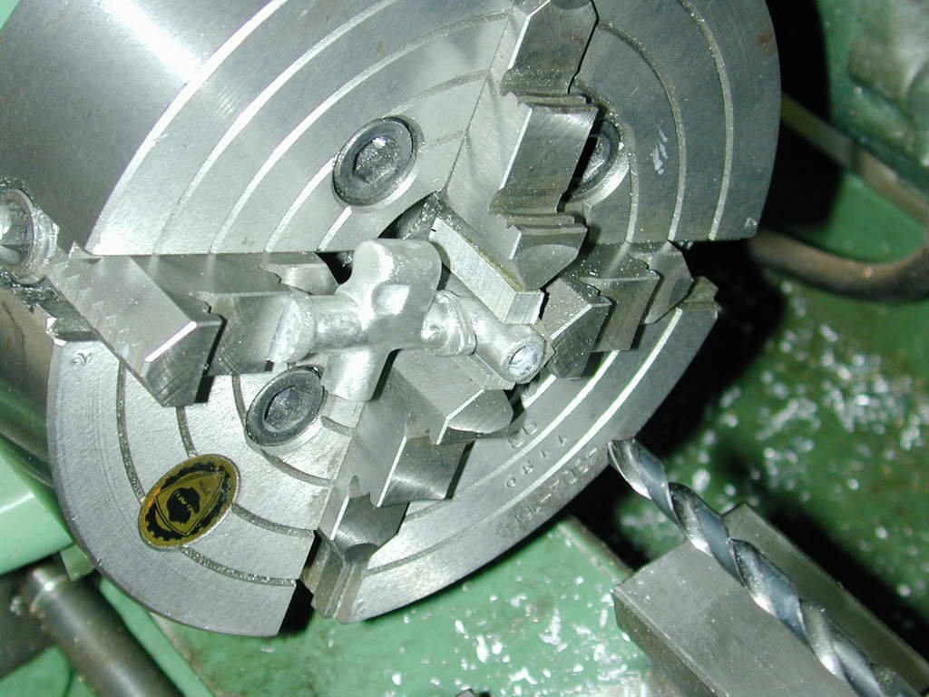 Photo 10 |
 Photo 11 |
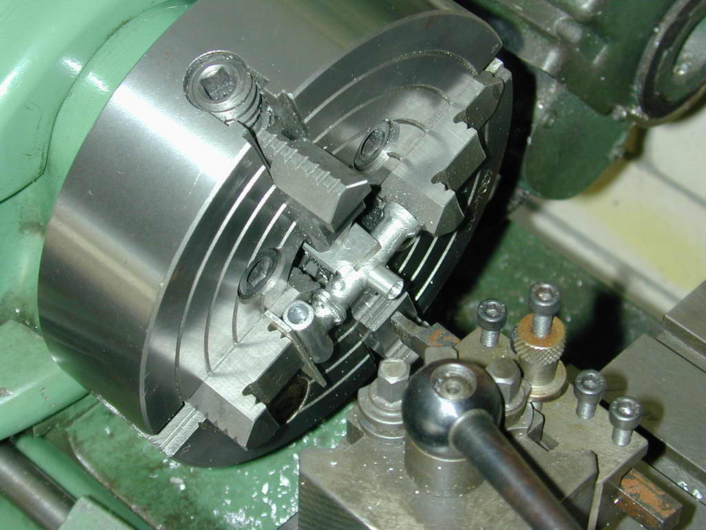 Photo 12 |
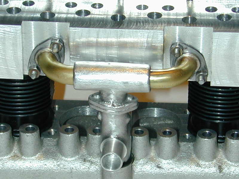
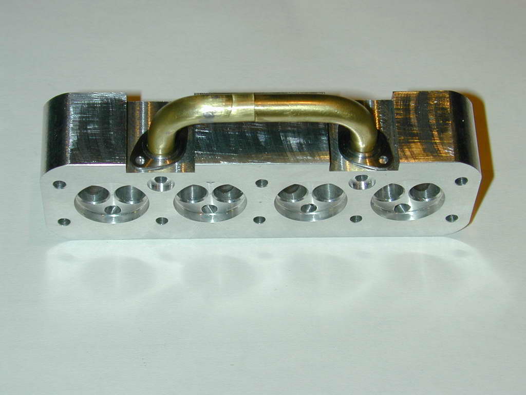
With the pipes inserted in the T casting, the position of the attachment holes were spotted through the flanges onto the head. Holes were than drilled and tapped 2-56 for studs that will carry the flange nuts. This looks more scale like and reduces the chance of stripping the threads to nearly zero.
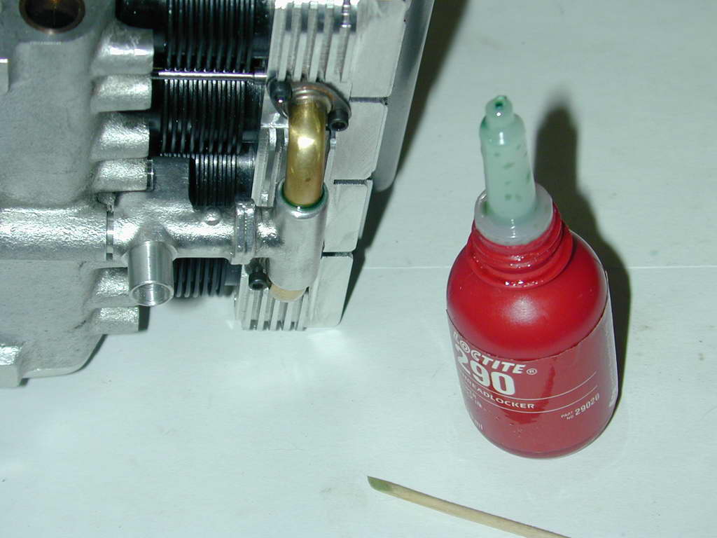
The lateral position of the T-piece has been correctly set by the elbow tubes and flanges. To set the longitudinal position, it is slid along the elbow pipes while the head is carefully screwed down in the right place. "Super-wicking" grade Locktite was then applied with a toothpick to the pipe/casting joint and allowed to cure. The space visible between crankcase and T-piece in this photo is for the O-ring that will seal the joint.
 And just in case you think this was all plain sailing, here's one of four tube bending stuff-ups. Amazingly, I bent two tubes one after the other with no problems, then broke four in a row trying to make neater, sharper bends. Finally I ran out of tube, gave up, and decided to use the first two made!

Back to Cirrus Main Index

This page designed to look best when using anything but IE!
Please submit all questions and comments to
[email protected]
Copyright (c) Ronald A Chernich, 2004-2006. All rights reserved worldwide.