Cirrus Construction Log: Cylinder Head - Part 2
Created: September 2006
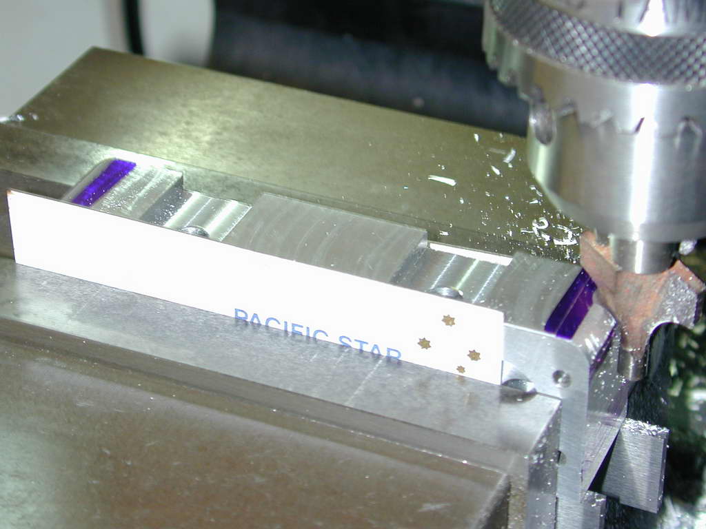 Photo 25a |
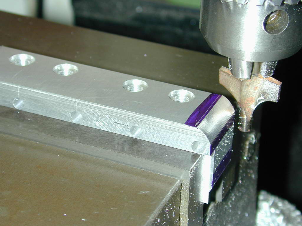 Photo 25b |
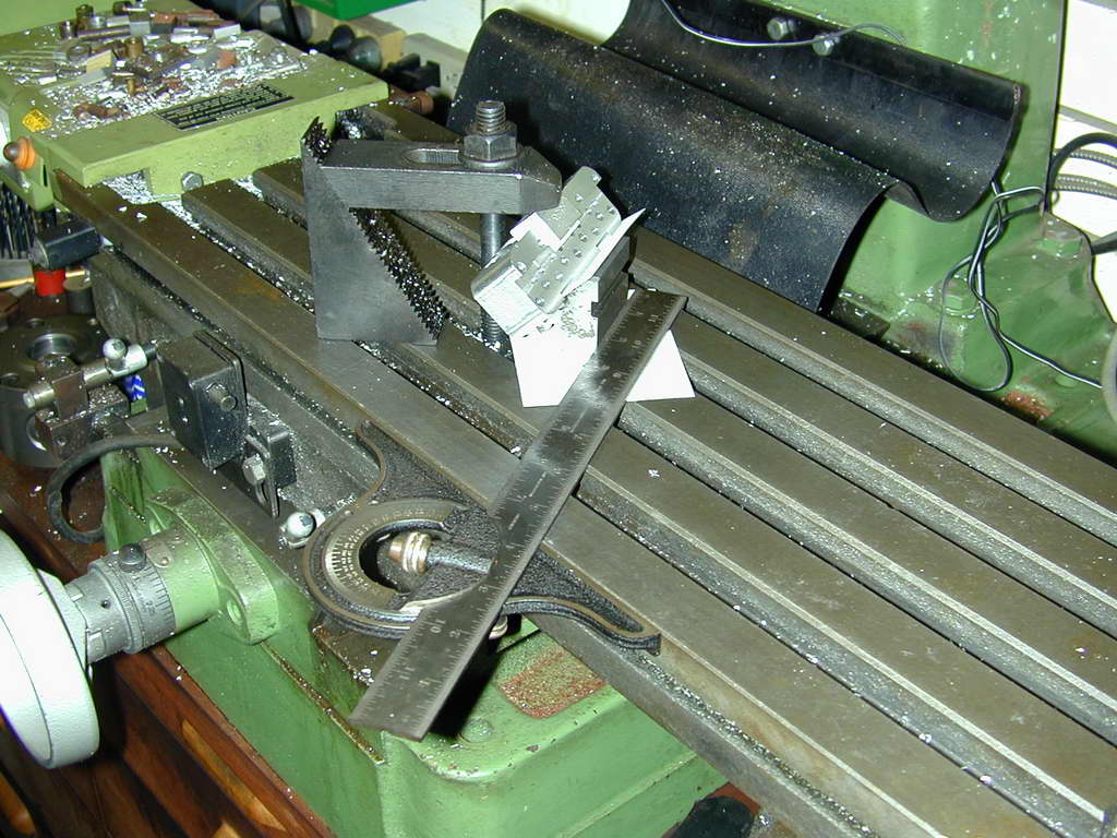 Photo 26 |
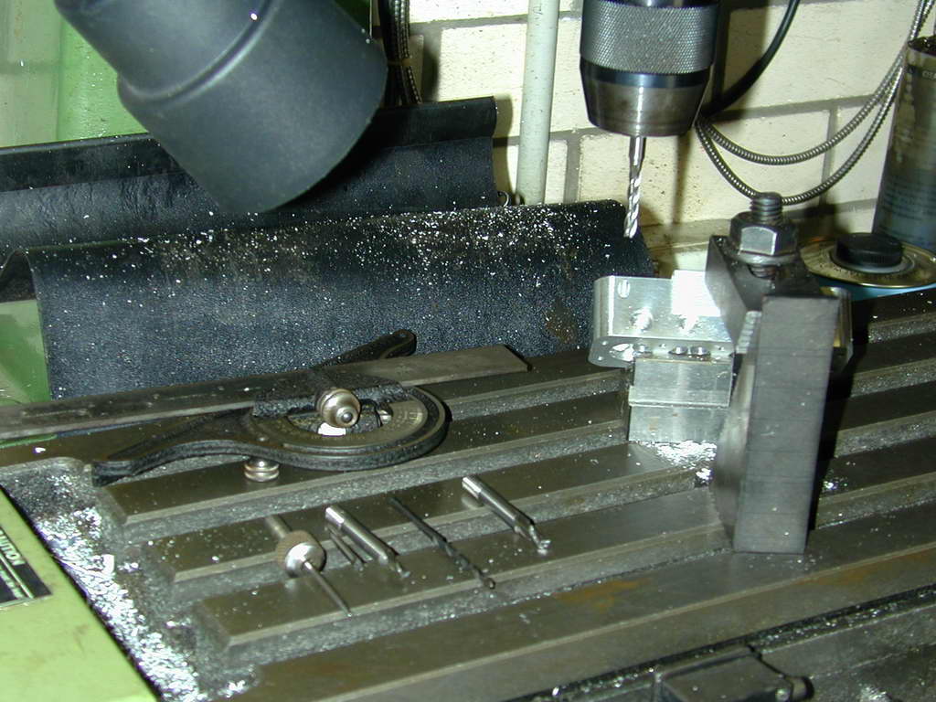 Photo 27 |
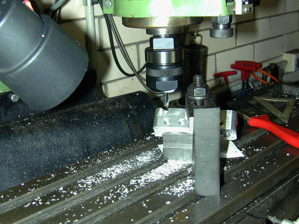 Photo 28 |
Photos #26...28 show exhaust ports being cut. Each port has a "pocket" for the exhaust manifold flange to bolt to. The actual ports are drilled at 45° while the pocket are milled at alternately plus and minus 30° to the longitudinal axis. One way (described by the Whittle SIC construction series) is to set over the mill head. I chose to jig it all up using V block to give the 45° and a protractor to clamp the V block at 60° to the X axis. A "sticky pin" was used to pick up the marked out entry point for the port axis (Photo #27). An end mill was then used to cut a flat for the center drill. After drilling through to the valve pocket, a slot drill was traversed along the X axis to mill the pocket so its outside edge would just meet the yet-to-be cut upper cooling fin.
Tip: The pocket dimension shows in SIC is longer than it needs to be, and the between bolt hole distances of the flanges is too short to use studs an nuts (no room for the required box spanner to tighten them). All could be adjusted.
All the drilling and milling is now complete with the exception of the tapped holes to attach the exhaust and inlet manifolds. These will be spotted from the manifolds later, so we might as well make one last try the stuff the job by slitting the fins.
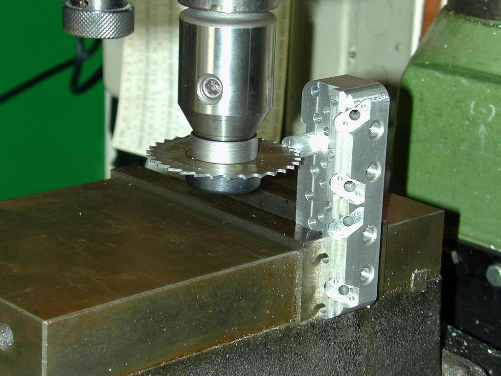 Photo 30 |
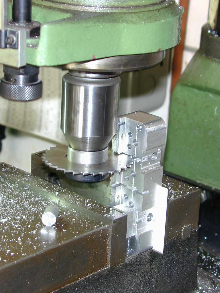 Photo 31 |
First task is to simulate the four separate heads by cutting "separation channels" that line up with the three middle pairs of hold-down bolt holes. The simplified saw alignment, I made a little plug that fits into the counter-bore recesses of the head bolts. The plug has a slot cut across the diameter on its end. This was just pushed into a counter-bore and the saw aligned in the slot (Photo #30). This worked fine.
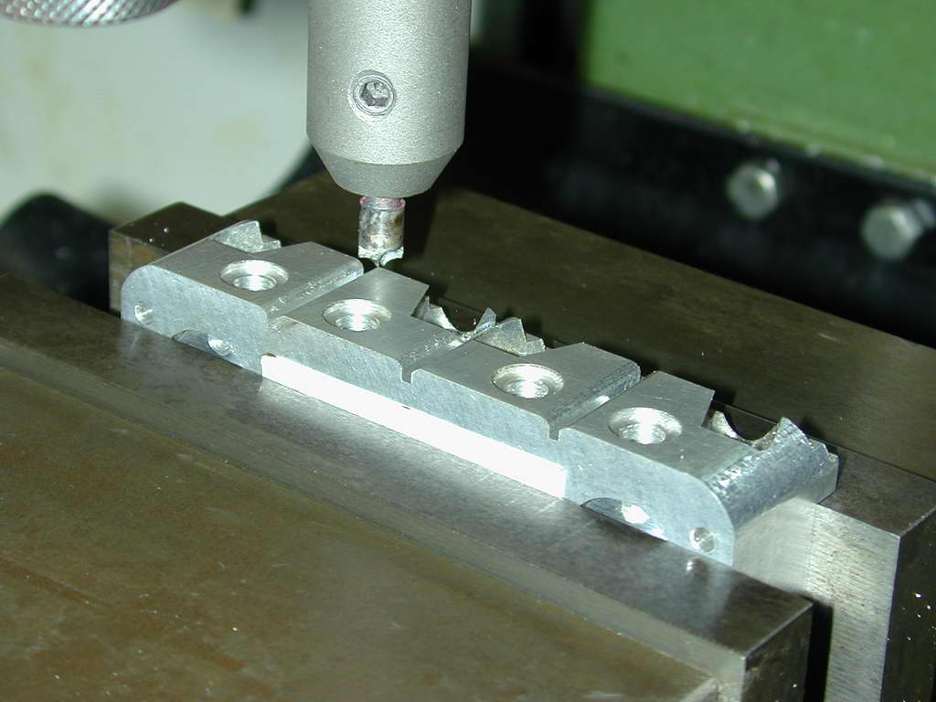 Photo 32 |
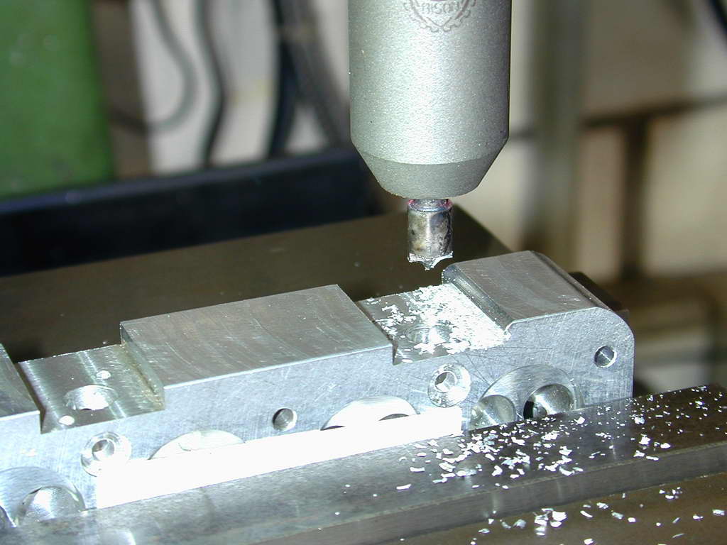 Photo 33 |
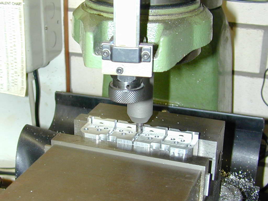 Photo 34 |
There's a last edge rounding job to do that requires a 3/32" radius cutter. The router bit design had worked so well, I made a replica from 1/4" drill rod. Relief was filed in before hardening and tempering. Without dressing up a very special grinding wheel less than 3/16" in diameter, I could see no way to sharpen this cutter, so I just relied on the edge left by milling the tow flutes. Remarkably, it worked fine and did the job just like its big commercial brother, even rounding the "blind" slots on the top of the head that I had no chance of getting a file into (Photo #33).
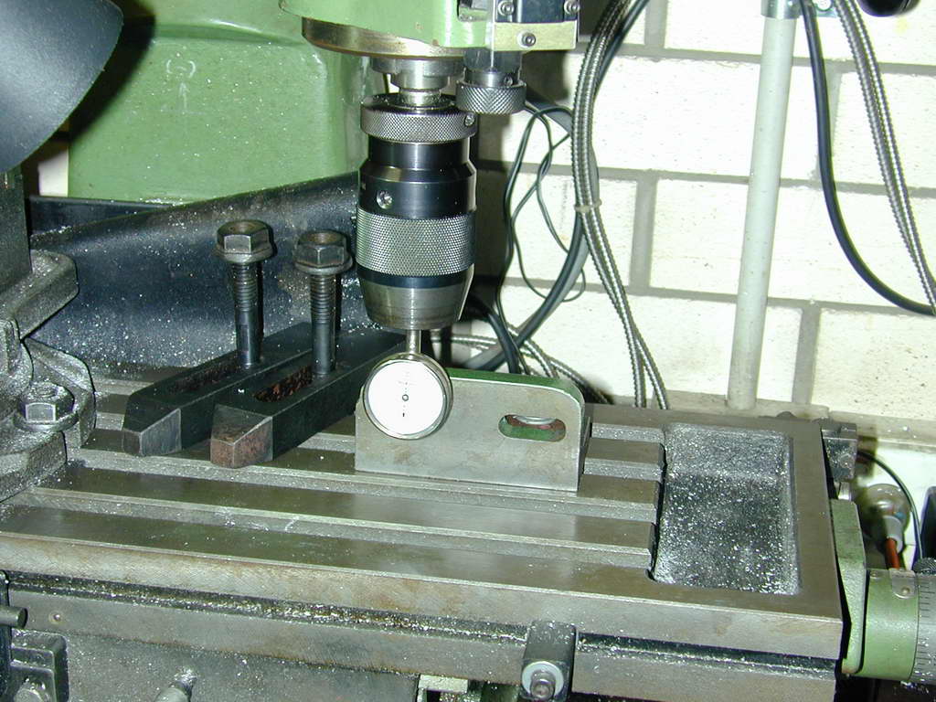 The fins require a rather small diameter saw to get into some tight spots as shown on the SIC plan. To hold the work for this job, my small angle plate was bolted to the mill table and aligned with the X axis as a back-stop for the head.
Planning for the fin cuts took almost as long as cutting them. Using CAD, a "cut plan" was devised by moving a circle representing the cutter around and measuring the X-Y offsets of the circle center relative to the left hand and front head faces. The plan called for cutting all fins on one end and one face, then reversing the head and repeating the sequence to cut those for the other end and other face. The ends used the same offset plan, but the exhaust and inlet faces needed different depths. The DRO on the quill down-feed *should* ensure repeatability and the two set *should* meet up. The references for the plan called for the saw to zeroed X-Y at the points where it just kissed the faces. The plan looked something like:
| Both Ends: |
| 1. Y ^ 2.095, Cut X > 0.265 |
| 2. X > 0.045, Cut Y v full width |
| 3. Y ^ 1.250, Cut X > 0.115 |
| 4. Y ^ 0.408, Cut X > 0.265 |
| ... |
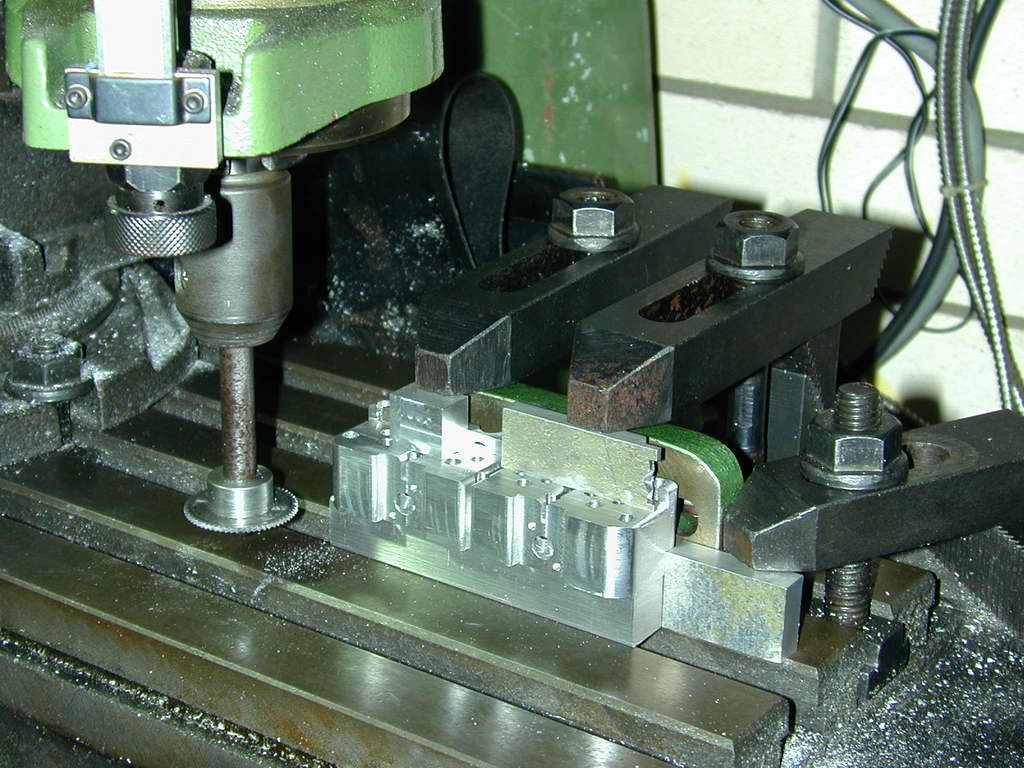 Photo 36 |
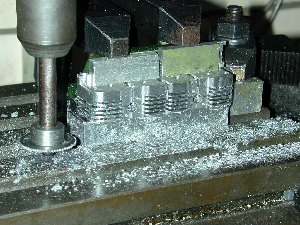 Photo 37 |
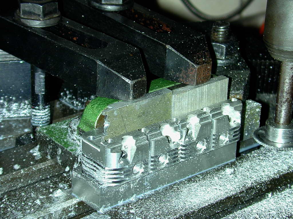 Photo 38 |
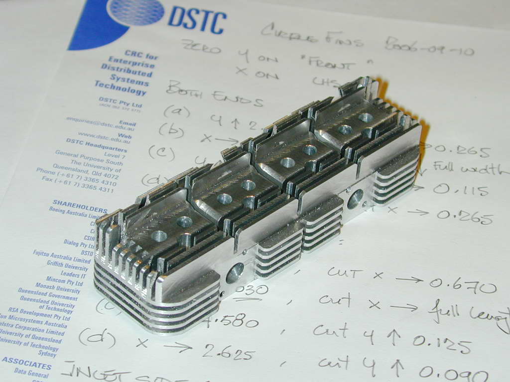
Photos #36..38 Show one end and inlet manifold side fins being cut. In Photo #36, the cutter on the home-made mandrel has been lowered to just touch the sacrificial block the head is resting on that allows the bottom fin gap to be cut. This Z axis reference establishes the reference that must be returned to for the second set of cuts. The clamping arrangement is not ideal; the clamp bolts should be as close as possible to the clamp point, but the set-up prevented that. Note also the separate end stop clamped down at the right to assist positioning when the head was reversed. Photo #37 shows the inlet side complete, and #38 the exhaust side. The fin line-up is as near to perfect as could be wished for.
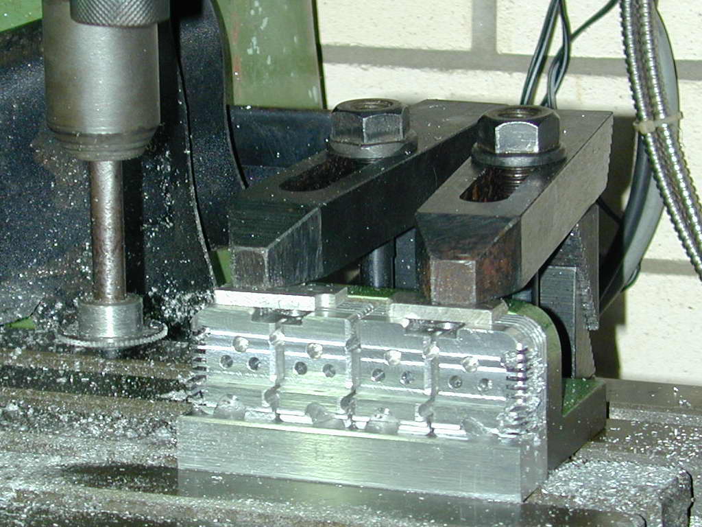 Photo 39 |
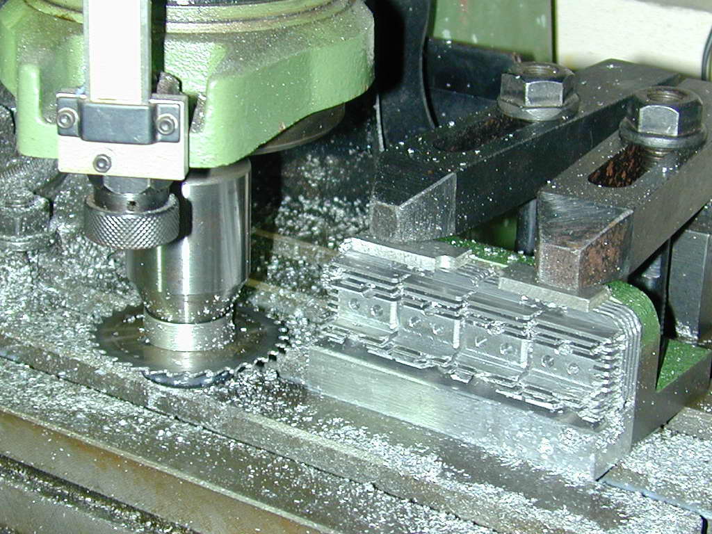 Photo 40 |
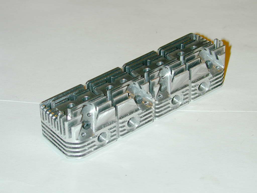 Photo 41 |
The top fins required another plan, but no "flipping". The small diameter saw was used on the front and back faces to emulate longitudinal fin gaps. Cutting the full length fins required a different cutter as the little cutter would not reach the depth required. The eagle-eyed will not cutting fluid residue in these photos. The slitting saw produces an aluminium powder that coats everything and if allowed to get into the cut, badly galls the finish. Squirting cutting fluid onto the saw clumps the dust up allowing it to be flung away producing a FAR superior finish than a dry cut.
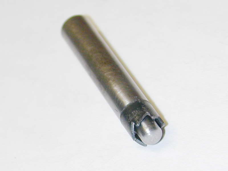 Photo 42 |
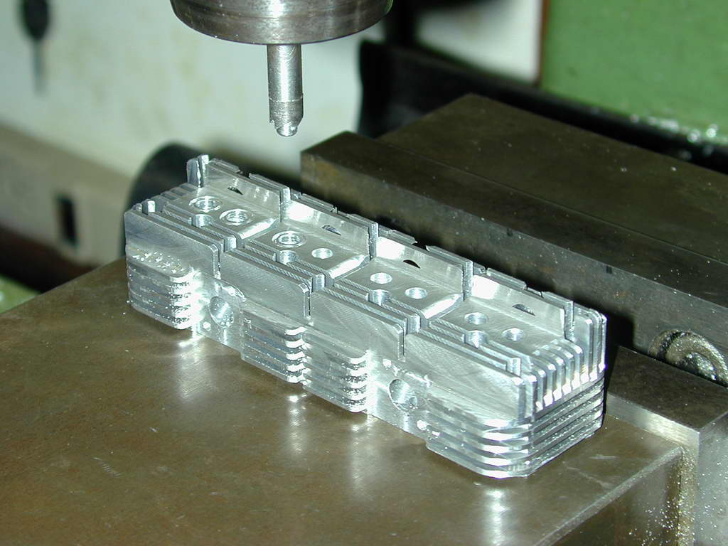 Photo 43 |
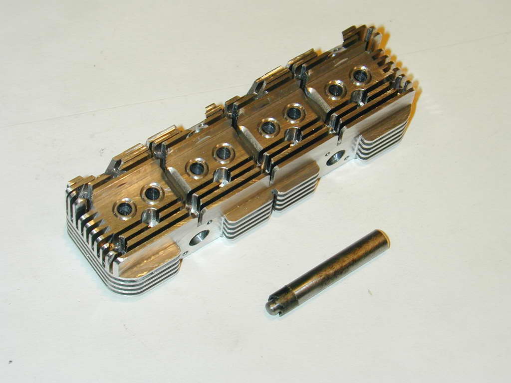 Photo 44 |
After drilling and tapping for the manifolds, the last job on the head is to mill a 1/4" recess 0.015" deep to center the valve springs. To ensure concentric alignment, I made a little piloted cutter. Rather than have a simple counter-bore, I decided to make it like a little hole-saw to produce channels for the springs. This was not as much work as it looks. a little ring of 1/4" drill rod was formed by counter boring and the teeth filed by hand; twice as it turned out, as the first lot faced the wrong way! The hole saw ring was parted off, hardened and tempered, then Locktited to the pilot mandrel. It really did not take long to make. Photo #43 shows it in use (the head being allowed to float). Photo #44 shows cutter and end result. The effect is very satisfying and certainly worth the extra effort.

Back to Cirrus Main Index

This page designed to look best when using anything but IE!
Please submit all questions and comments to
[email protected]
Copyright (c) Ronald A Chernich, 2004-2006. All rights reserved worldwide.