Cirrus Construction Log: Exhaust Manifold
Created: September 2006
In contrast to the Inlet Manifold, the exhaust manifold was rather simple to make even though it looks a bit daunting. It comprises four stub tubes made by drilling out drill rod, four flanges drilled and profiled from 0.050" thick stainless steel, a header pipe again made by drilling out drill rod, and a close-off plug for the latter. The SIC plans show the header as a constant diameter, but the Zimmerman plans show a tapered end which forms bit of a restriction and adds, in my humble opinion, to the aesthetics of the assembly.
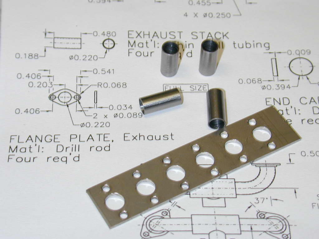 Photo 1 |
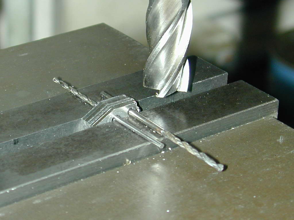 Photo 2 |
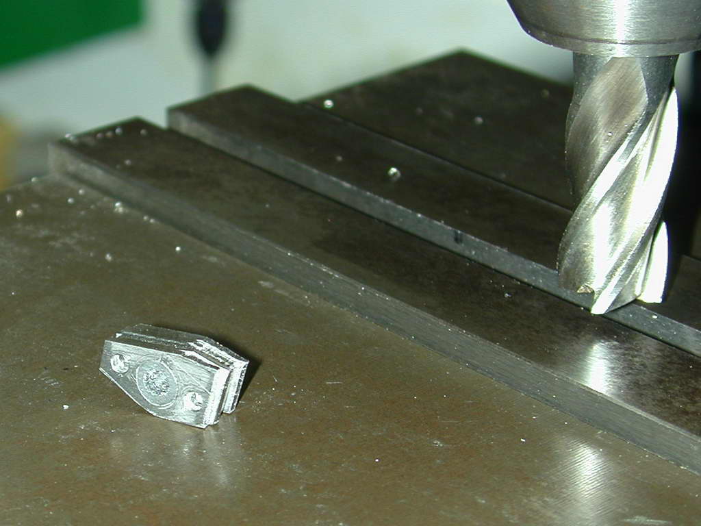 Photo 3 |
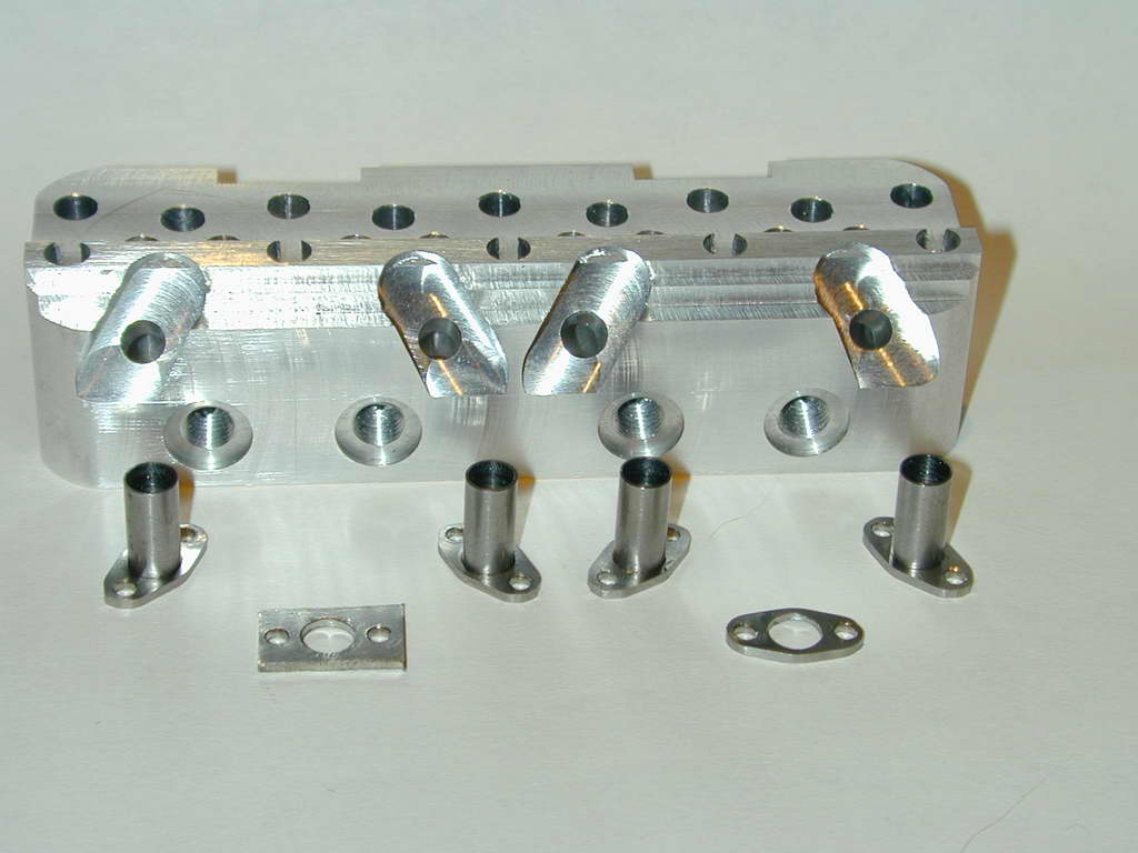 Photo 4 |
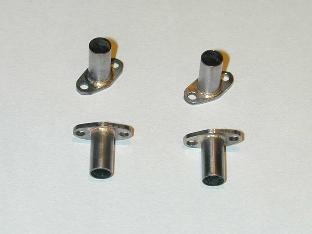 Photo 5 |
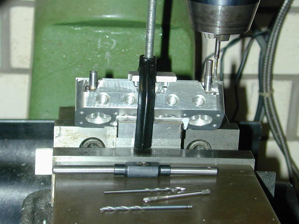
The flanges were co-ordinate drilled, the rough sawn into blanks that were threaded onto a hollow mandrel (Photos 1 and 2). By carefully selecting drill sizes to insert through the mandrel and mounting holes, the stacked blanks can be precisely and repeatably aligned to mill the sides of the flanges. A final set of cuts with the quill locked produces fully symmetrical flanges. Final rounding is done by hand with a file. The exhaust pipe stubs can then be silver-brazed to the flanges. The extra flange will be used as a template to cut the gaskets.
To ensure that the stubs positioned perfectly over the head ports and that the holes in the header pipe then perfectly fit over the stubs, the following sequence was devised.
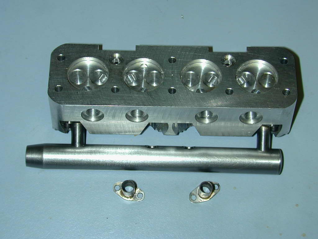
 First a 3/16" rod was inserted in the front and rear tubes to align them with the exhaust port holes in the head. These ports are on a 45° face, so the head was supported in V-blocks for spot the attachment holes through the flanges. Only the end pipes were attached; the center pair will be done later.
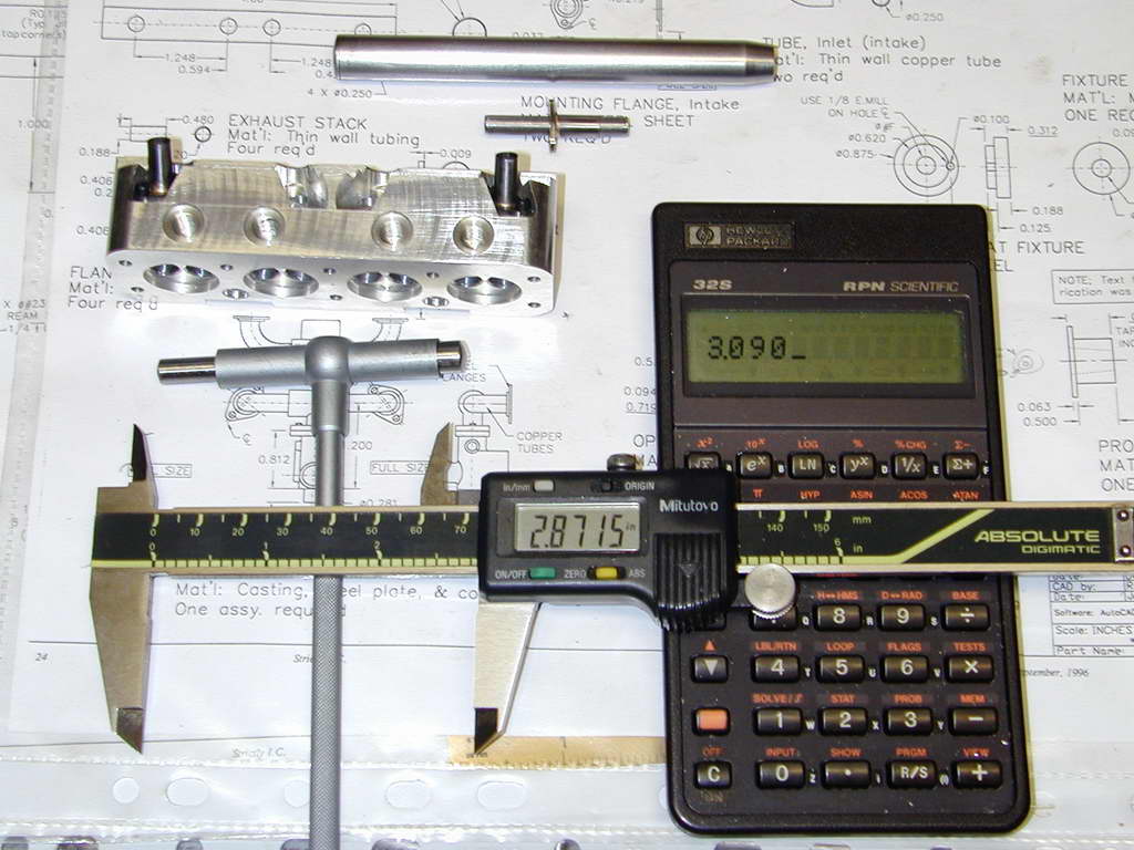 With the two stub pipes firmly screwed in place, the precise center to center distance was established by measuring the distance between the inside faces of the pipes, then adding the diameter of one pipe. The 3/16" rod was then inserted in the two open exhaust ports to establish the distance from each to one of the end pipe centerlines.
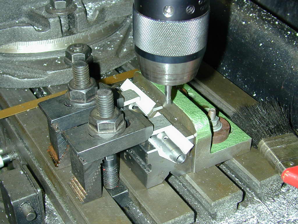 After drilling out the header (much more swarf than part), it was clamped in V blocks that were aligned with the X axis of the mill by an angle plate that had been squared with a DTI. The Y axis was centered over the header by kissing it with a small milling cutter (2mm) and centering over the tiny mark produced. Holes for the exhaust stubs were then drilled in the header at the positions determined in the previous step.
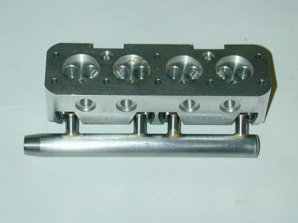
 The moment of truth: the header fits absolutely perfectly over the two fixed pipes. Due to the way the exhaust ports where drilled in the head, they may not be perfectly in line, even though any miss-alignment will be small. But as there are only two pipes involved at the moment, this does not matter.
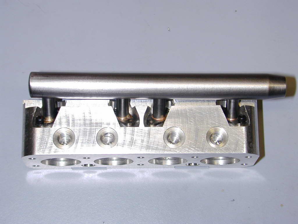 The header was then removed and the two center stubs were then inserted. I should note that the holes for the stubs had been drilled to be a very close fit in around the stub pipes, so they were quite happy to sit where they were put. The header was then replaced over the end pipes and the position of everything aligned to the required heights and orientation.
Photo 11 shows the header and stubs all fluxed and ready for silver brazing. In the SIC article, Eric Whittle went to enormous effort to melt, cast and turn silver-braze rings to slip over the pipes. He also used the head to jig the tubes during brazing. I truly did not like that idea.
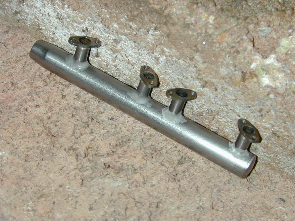 Photo 11 |
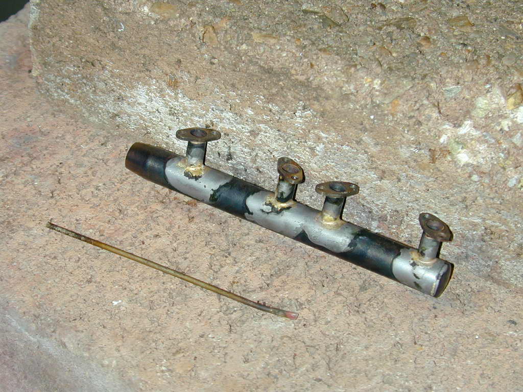 Photo 12 |
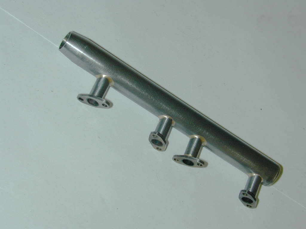 Photo 13 |
I trusted my skill and luck. With a good, hot, focused propane flame, each joint was heated until the flux sublimated (goes liquid), which is near red heat. Touching the silver-brazing rod lightly to the intersection forms a small pool that almost instantly flows around the joint. Viola! Four perfect joints. As you can see, the assembly was fully self-supporting during brazing. And as you can imagine, this relies very heavily on the fit of the tubes in the header holes. To be safe, the heat was applied first to the stubs so they would expand into the header. Much better than having the header expand away from the stubs!
 After cleaning up, the exhaust manifold was re-attached to the head by the end flanges. The holes for the middle pipes could then be spotted through their flanges for drilling and tapping. If these are a couple of thou off in relation to the ports in the head, it will never be noticed. In the event, they lines up better than I had any right to expect.
Conclusion
I made the flanges and "pockets" in the head precisely to the SIC plans. These are slightly different from the Zimmerman plans which have the pockets at 90° to the axis of the engine. The SIC drawings slant them 30° to the axis. I think the SIC drawing results in a neater look. But the flange holes are too close to the stub pipe to use studs and nuts and still get a box spanner in to tighten them. Conversely, the pockets are longer than they need to be for the flanges by almost 1/16" (1.5mm) at each end! Doing it again, I'd make the flanges longer so that nuts and studs could be used and reduce the pocket length, rotating the flanges more in the pockets to fit them in.

Back to Cirrus Main Index

This page designed to look best when using anything but IE!
Please submit all questions and comments to
[email protected]
Copyright (c) Ronald A Chernich, 2004-2006. All rights reserved worldwide.