Cirrus Construction Log: Cylinders
Created: April 2005
For the Cirrus cylinders, I borrowed a tooling idea from the Hodgson Radial plans, the result appearing in Photo #1 below. This worked very well and more than repaid the time required to build it for a number of reasons.
 ).
).
Second, it makes a good go/no-go gauge to get all the cylinder bores to within tenths of the same size, allowing the same size piston rings to be used for all cylinders.
And finally—a surprise—it saved the fin cutting tool from a potentially disasterous "bang" situation when, after becomming blunted, it dug in. Instead of the turning work breaking the tool and destroying some fins, it simply slipped arount the still turning mandrel! A real life-saver.
The four cylinder blanks (12L14) were bored to a close slip fit on the polished mandrel. The lower skirt and face of the mounding flange were turned at the same setting to ensure correct alignment to the bore (photo #2), although this could theoretically have been done on the mandrel. A 0.100" parting tool was used to rough out the gap above the mounting flange, then a radiused tool used to finish this area and lightly skim the fin area (photo #3). The bottom of the lower fin was very carefully indexed from the lower mounting flange face to get the location of the last fins to come out at as close to the same height as possible.
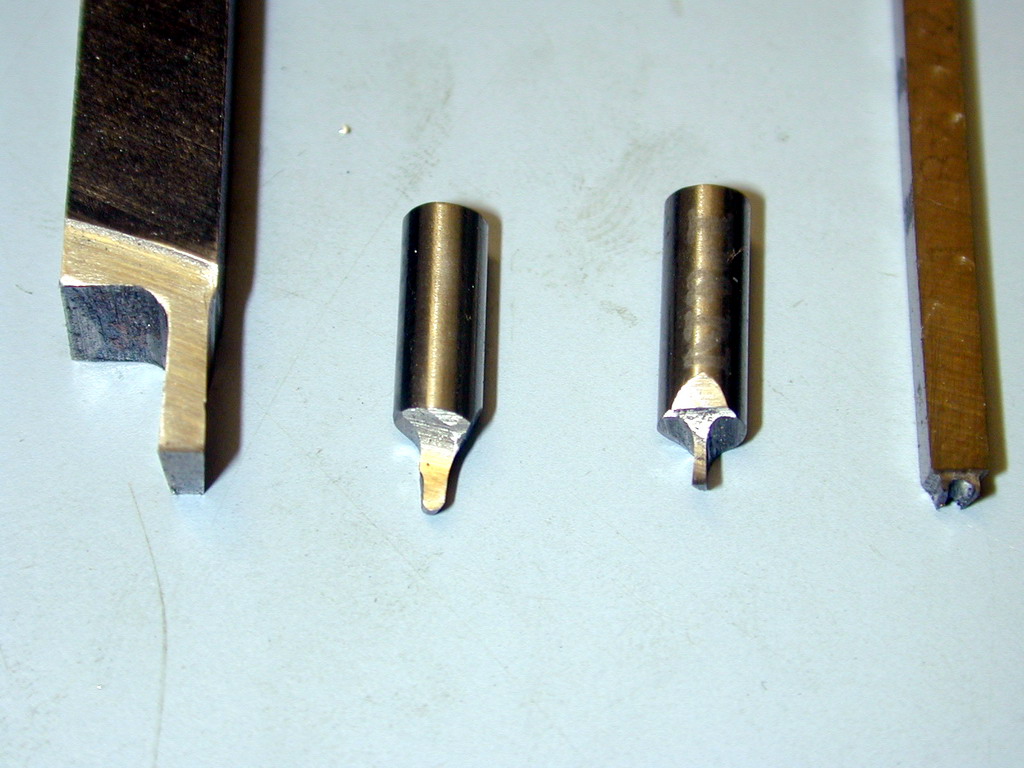
This photo shows the tool bits used to machine the mandrel mounted cylinders. The first two tools from the left are those described above. The next two were used to produce the fins. The fins and gaps are each 1/32" wide. The fin depth is over 0.1". Four cylinders (36 plunging cuts) is a lot to ask of a narrow HSS tool, but the "auto-slip" feature inherant in the mandrel setup as described above let me know when a touch up was required (twice, is the answer). After all cylinders were finned, the tool on the right was used to profile the fin tip. Look at photo #7. The outer pair have been profiled. The inner pair are still square tipped. The improvement in appearance may not be so apparent here, but in 'real life' it's chalk and cheese. Well worth the extra effort and far superior to using a file and emory paper (faster too).
The final operation is to mill flats that allow the closely spaced cylinders to drop into their crankcase bores. Making the first cut was a tense moment, but no problems were encountered—cutting from side to side, naturally.
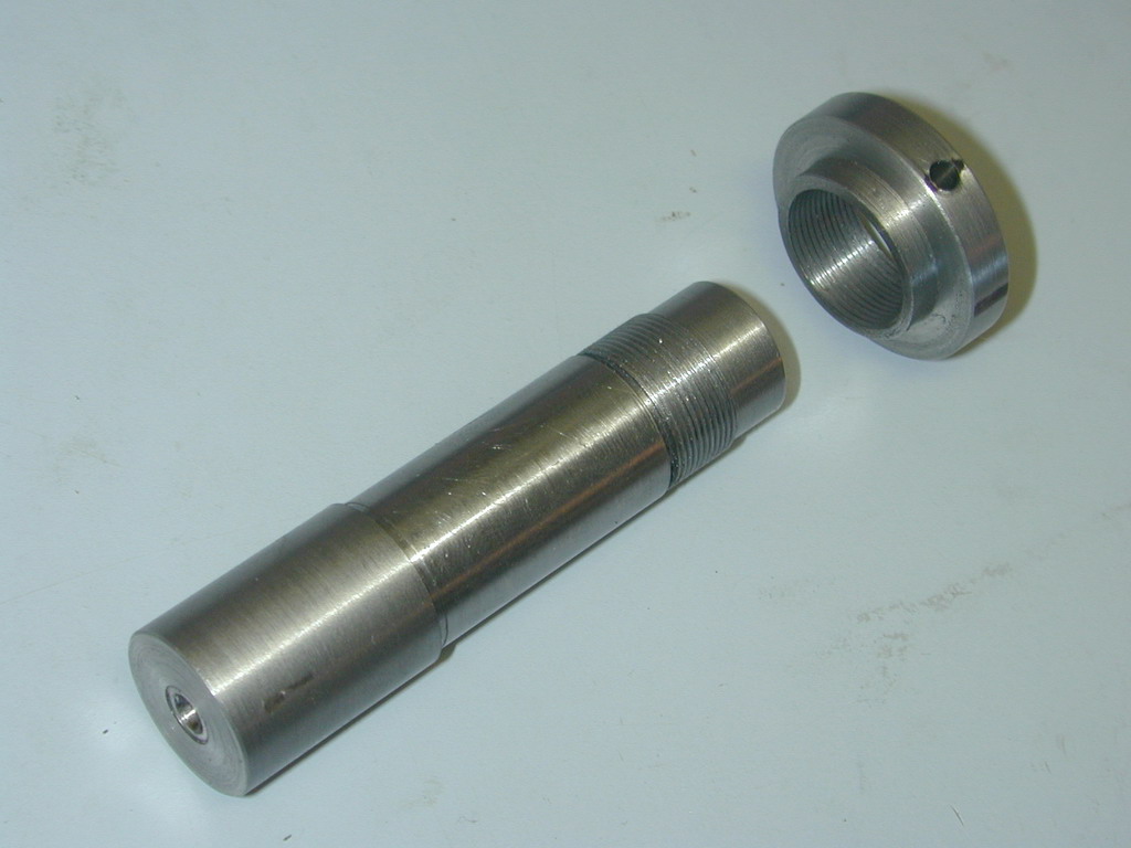 Photo 1 |
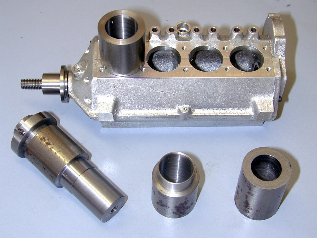 Photo 2 |
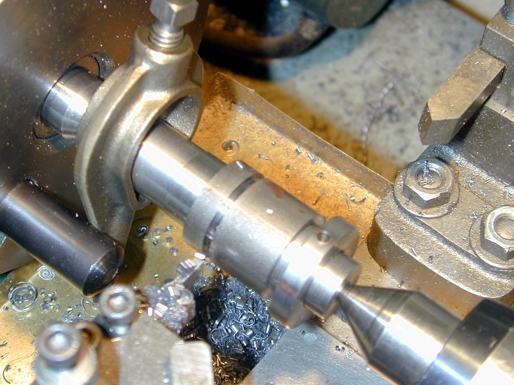 Photo 3 |
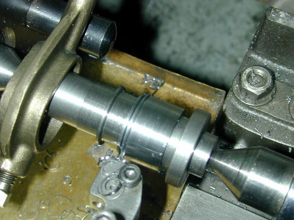 Photo 4 |
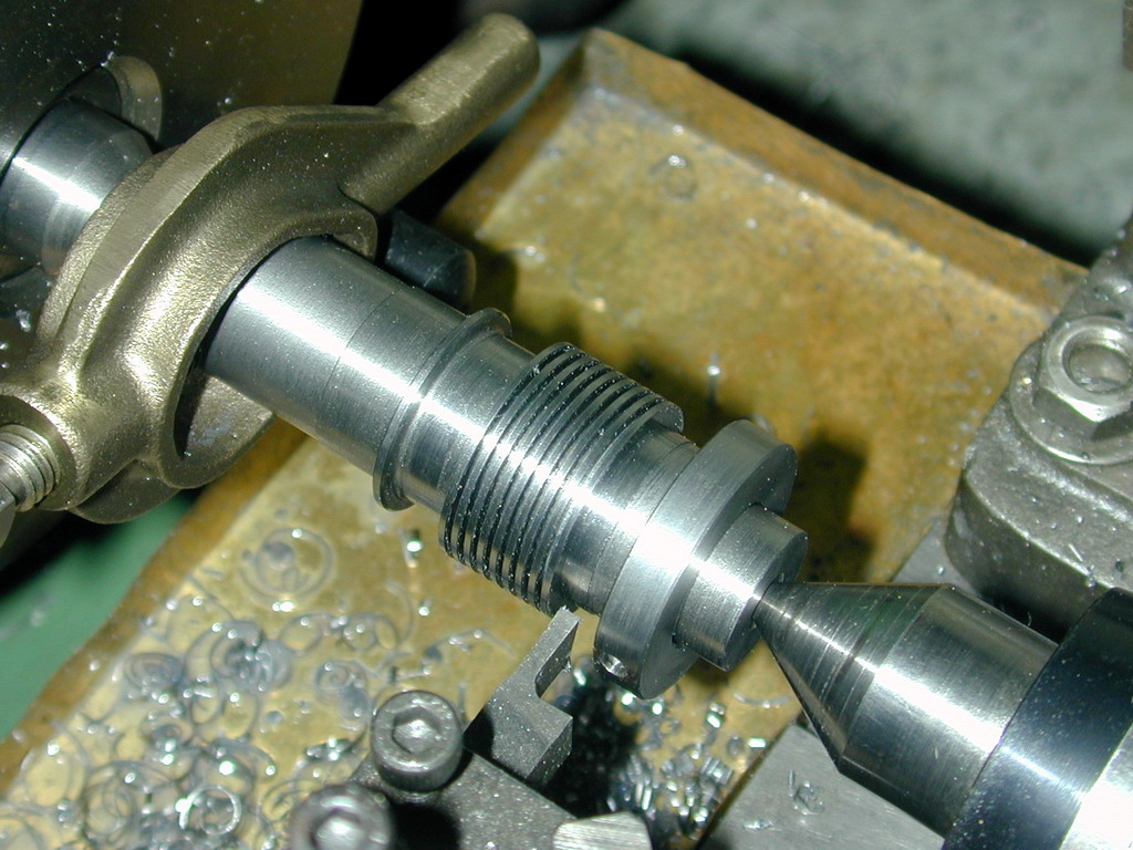 Photo 5 |
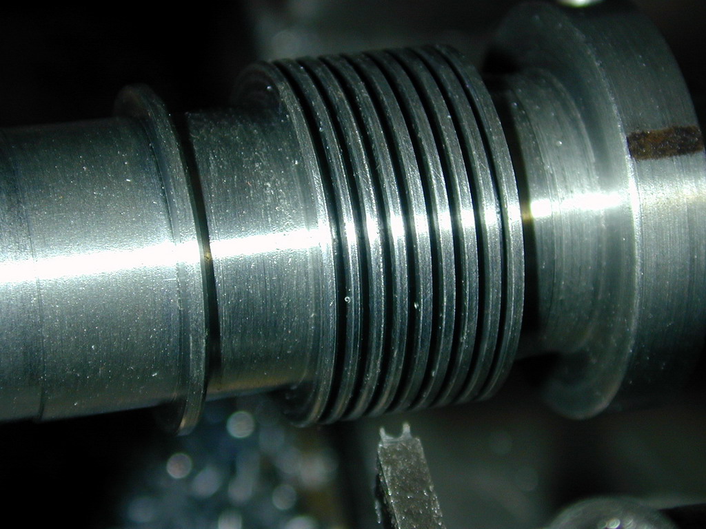 Photo 6 |
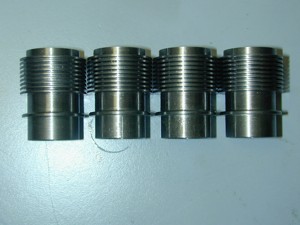 Photo 7 |
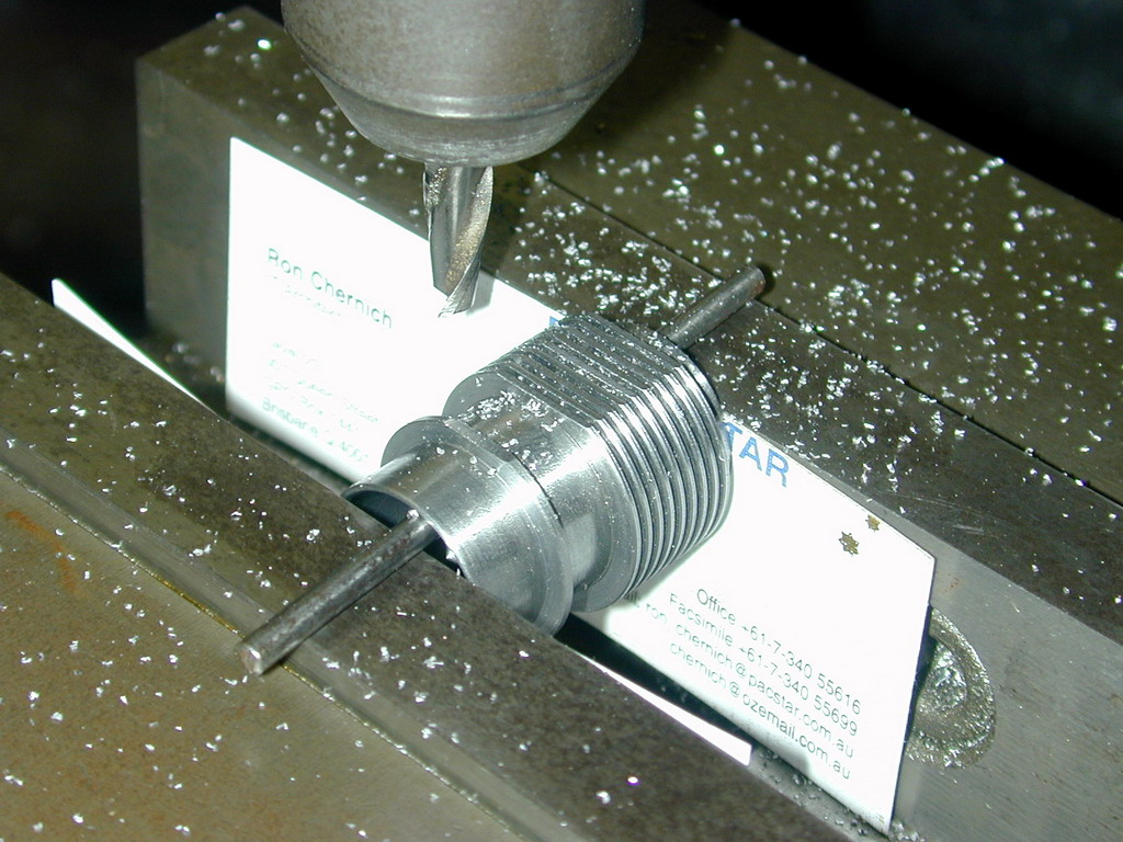 Photo 8 |
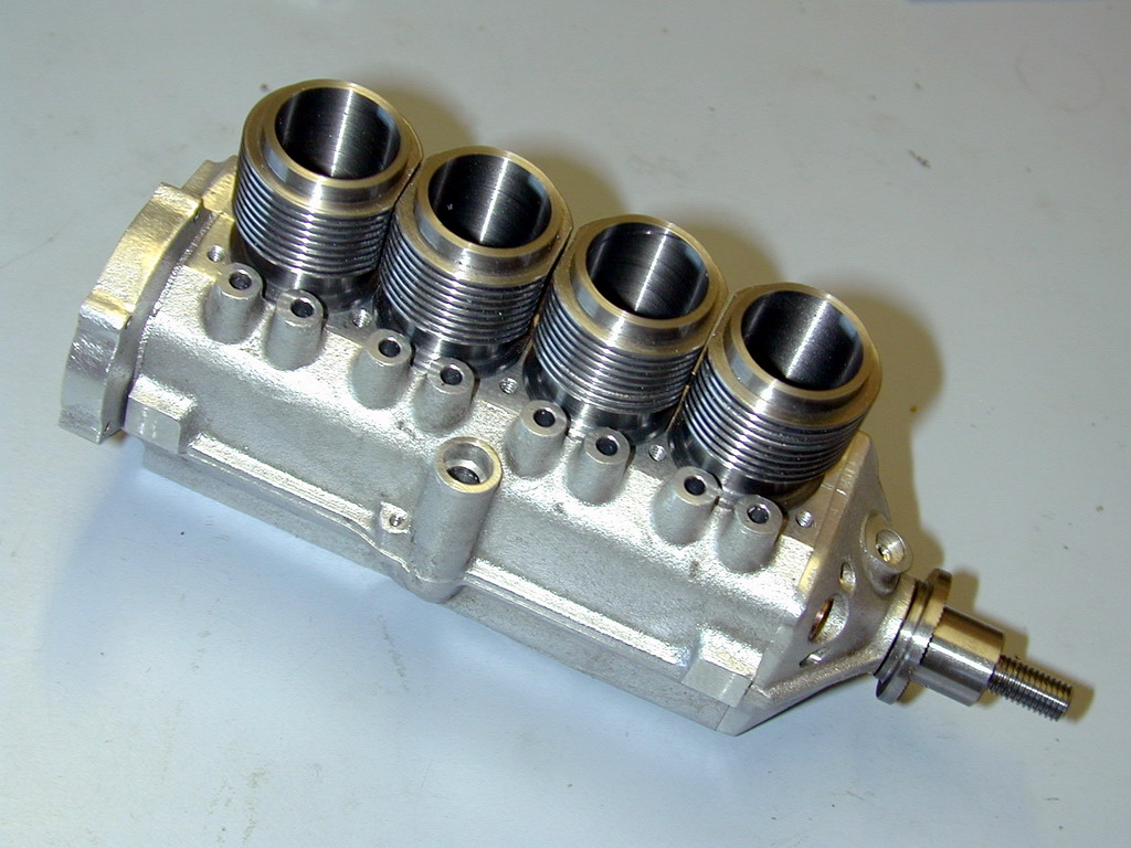 Photo 9 |
As designed and drawn, the lower cylinder spiggot has 0.007" of slop when fitted into the cylinders openings. The cylinder head presses against the top of the cylinders, just like some full-size auto engines. That is, the cylinders do not locate into the head. To get a gas tight seal, the tops of all the cylinders need to be ground (or milled) flat with them all pressed firmly down against the crankcase. To keep them all in line, a "spiggot plate" with closely fitting bores slips over the top of the cylinders. The "slop" mentioned earlier is to allow the bottom the the cylinders to float to where ever the plate wants them to be.
I was less than keen on this general idea, and figured that since the crankcase openings (and bolt pattern) had been coordinate drilled/milled using the mill DRO (digital read-out), I could make the spiggot plate to the same precision and life would be good—with no more than 0.002" float in the lower holes. What can I say? Worked perfectly, for once! The photos below show the mill being used to drill the bolt holes and center drill the bore locations. Photo #11 shows the plate being set up very accurately with a wobbler and a DTI on a faceplate for drilling and boring. Photo #12 shows the final product, after profiling the plate to resemble the lowest "fin" of four separate cylinder heads.
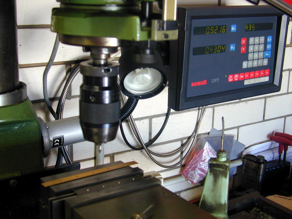 Photo 10 |
 Photo 11 |
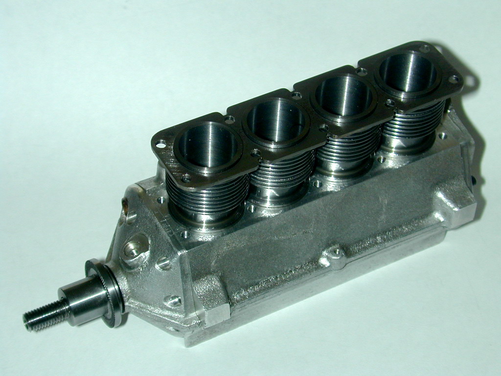 Photo 12 |
The remarkable thing about this set of operations is the time taken. To make the 'Hodgson' style cylinder mandrel: one evening of work. Machine the cylinders: one day. Make the spiggot plate: another day! Ok, maybe the second day was a bit shorter than the first, but it goes to show how a well made jig can speed things up, and how a simple, un-jigable task requiring high precision can take a disproportionate amount of time and effort.
It also shows the advantages of examining as many diverse sets of plans as you can, even if you don't intend to build the item in question. The cylinder jig described in the Hodgson 9 cylinder radial plans (which I fully intend to build someday) would not have occured to me, but is a terrific idea when producing multiple cylinders of the same type.


This page designed to look best when using anything but IE!
Please submit all questions and comments to
[email protected]
Copyright (c) Ronald A Chernich, 2004-2005. All rights reserved worldwide.