Cirrus Construction Log: Camshaft
 THIS PAGE UNDER CONSTRUCTION
Created: Feb 2005
The cams were cut using a table of "lifts" at four degree intervals produced by the CamCalc program available on this website. Note the laptop in the background of the third photo. It is displaying a spreadsheet of the lifts arranged so that all cams are correctly "phased" with respect to each other. I simply positioned the cursor in each column, set the rotary table position and mill quill height as indicated, made the cut, then hit Enter to move to the next value. When the cam was done, position to the next blank and the next column and repeat. Easy.
Photo #5 shows two scrapped camshafts. On the first (top), one blank got turned in the wrong place. The second got chopped off an inch short! (don't ask). I went ahead on that one and cut some trial cams. Just as well I did as they turned out to be phased for opposite to normal engine rotation! The jig shown in the SIC plan also had this small problem—later corrected in a Letter To The Editor by builder, Eric Whittle.
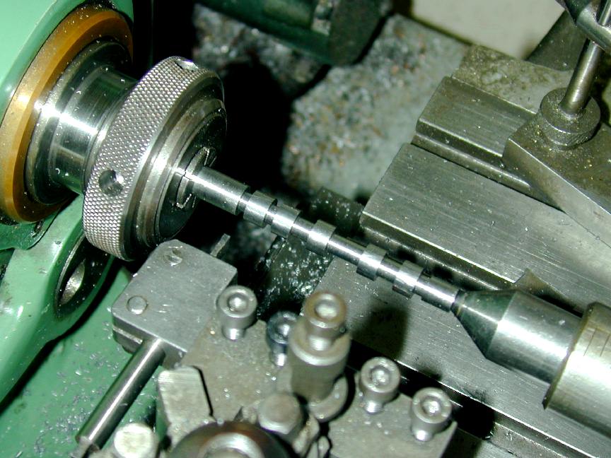 Photo 1 |
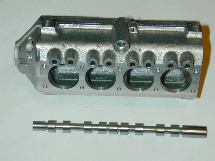 Photo 2 |
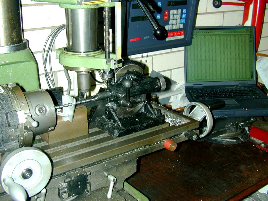 Photo 3 |
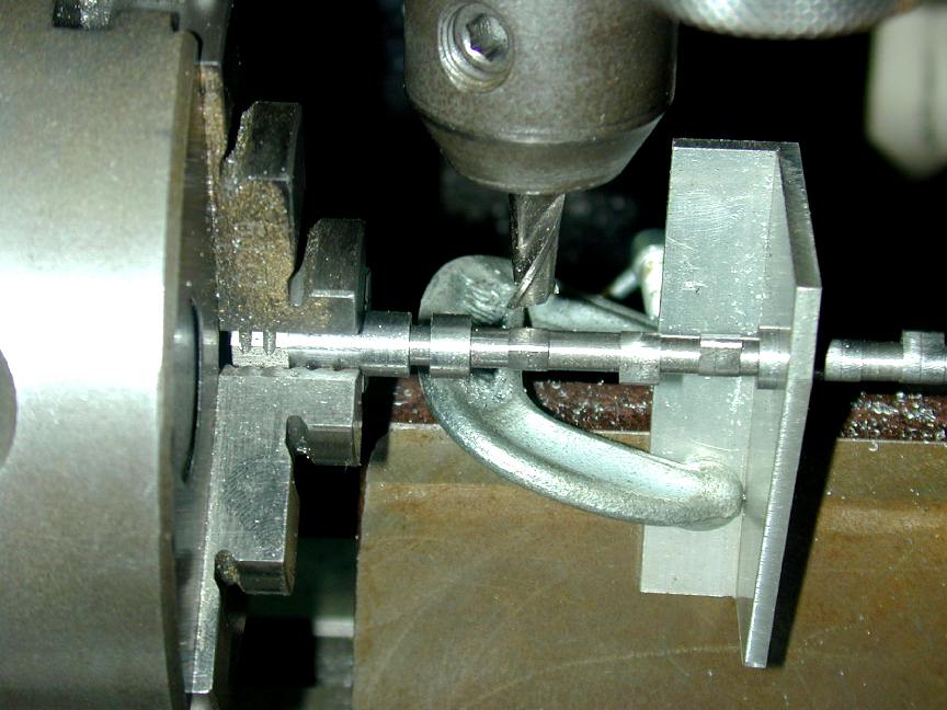 Photo 4 |
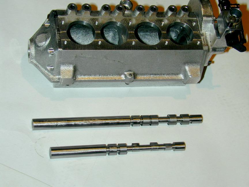 Photo 5 |
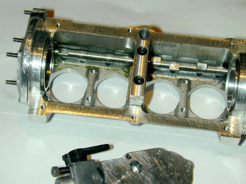 Photo 6 |


This page designed to look best when using anything but IE!
Please submit all questions and comments to
[email protected]
Copyright (c) Ronald A Chernich, 2004-2005. All rights reserved worldwide.