Vega 30
 |
 |
 |
| Name | Vega 30 | Designer | John Harbone |
| Type | 4-stroke, side-valve, glow ignition | Capacity | .30 cuin |
| Production run | Less than 100 | Country of Origin | UK |
| Photo by | Mark Thomas, David Owen, Eric Offen | Year of manufacture | circa 1988-1995 |
Background
The Vega range was designed and built from the late 1980's through to the the mid 1990's by John Harbone of Birmingham, England. His intent was to provide a range of engines for sport or scale flying that would be quiet and reliable [1]. They were manufactured in small quantities from bar-stock until ill-health forced an end to the venture. The rights to all the designs were sold on with the intention that they continue in production, but sadly, this did not eventuate.
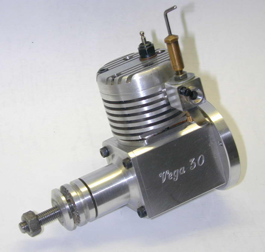
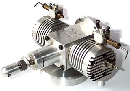 The initial models were all side-valve four-strokes typified by the .30 cuin model pictured above. The range also included a .61, .25 and a horizontally opposed, alternate firing twin using the .25 cylinders to give .50 cuin total displacement. Towards the end of production, .61 and .91 cuin displacement over-head valve (OHV) prototypes were made although they did not reach "production"[1][2]. All models are comparatively rare today, but they do appear occasionally as collectables.
| Model | Bore (in) | Stroke (in) | Weight (gm) |
| 180T | 1.064 | 1.028 | 994 |
| 91 | 1.064 | 1.028 | 714 |
| 61 | 0.870 | 1.028 | 685 |
| 50T | 0.700 | 0.634 | 462 |
| 30 | 0.780 | 0.634 | 334 |
| 25 | 0.700 | 0.634 | 322 |
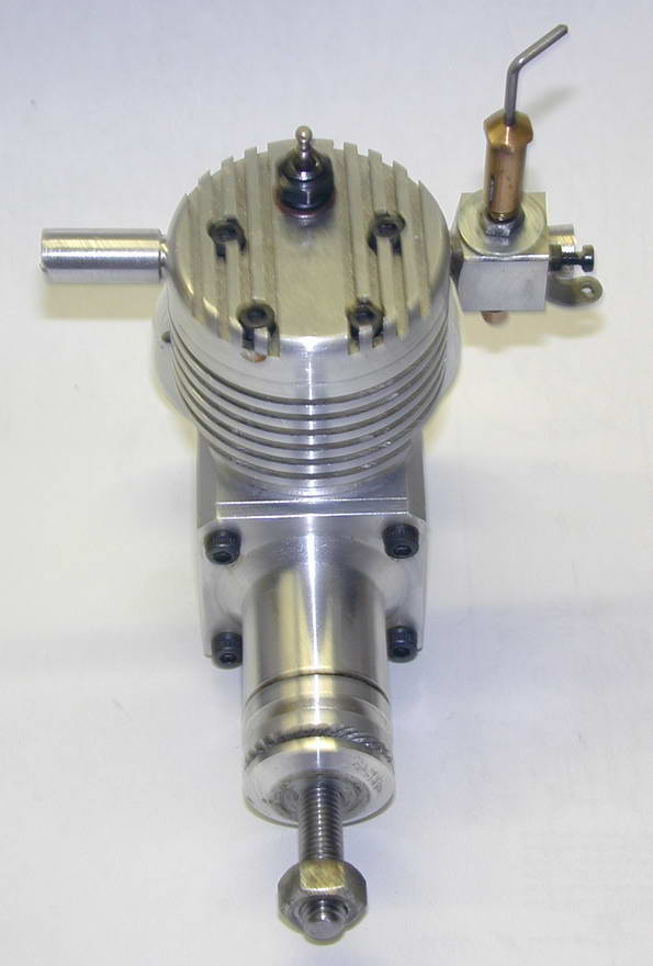
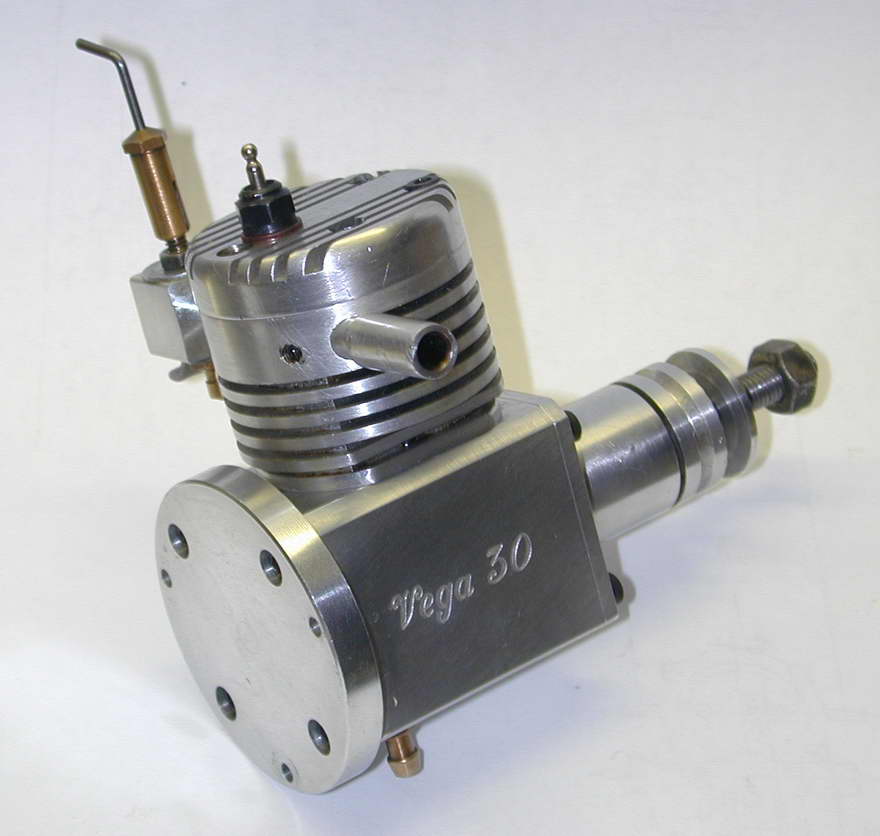
Each model was offered in two versions. On type "A", the carburettor and exhaust were oriented to the rear of the engine, while type "B" placed then on the side of the head. Company advertising stressed the enclosed valve gear, free from tappet adjustment, the compact size, "solid" (bar-stock) construction, quiet running, and ability to idle for long periods with instant throttle response.
Construction
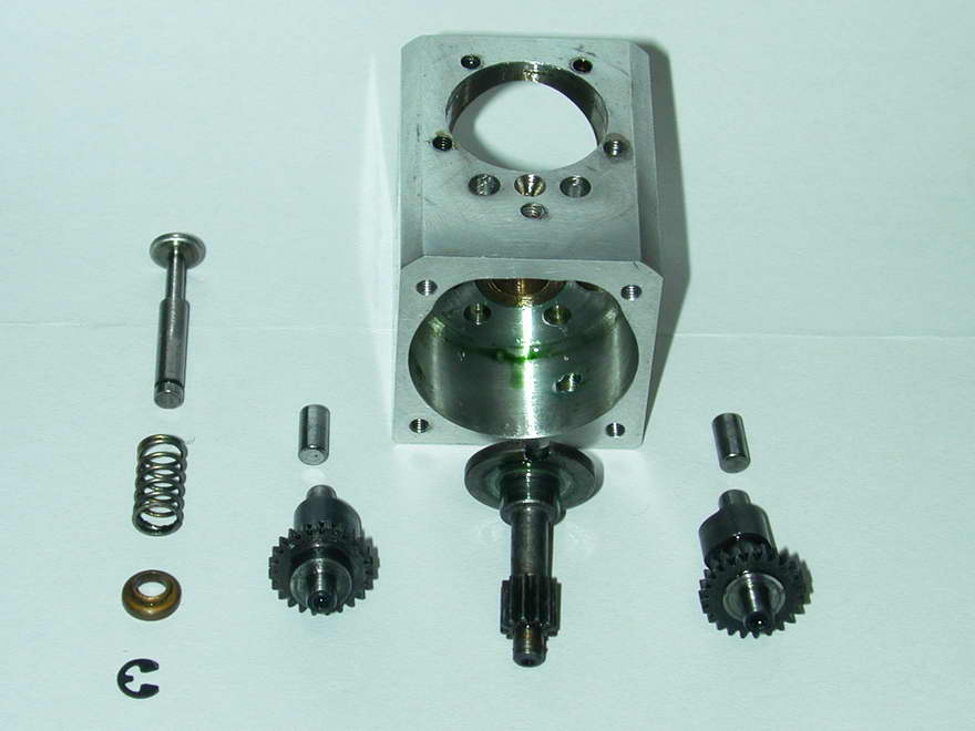
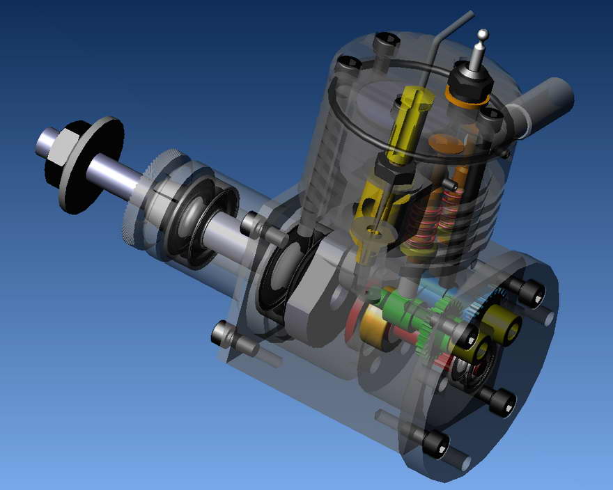
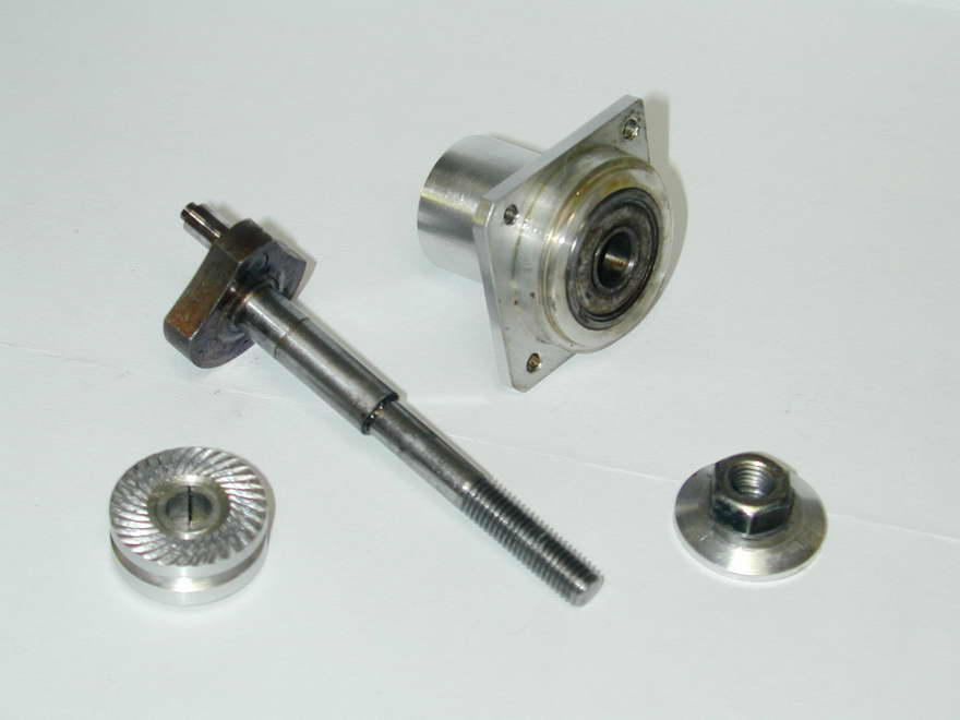 The design is really quite elegant. A conventional overhung crankshaft rides in twin ball bearings housed in a turned nose piece. The nose piece is secured with four screws to a square section bar that has been blind bored from both ends with the partition between the bores providing support for a follower shaft that engages the crankpin. The follower has a long spur gear to drive the cams with the requisite 2:1 reduction and is supported in a ballrace fitted to the engine backplate that doubles as the bulkhead mounting flange.
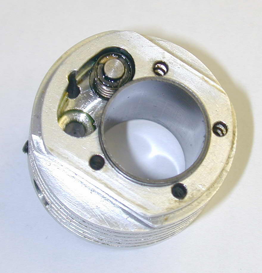
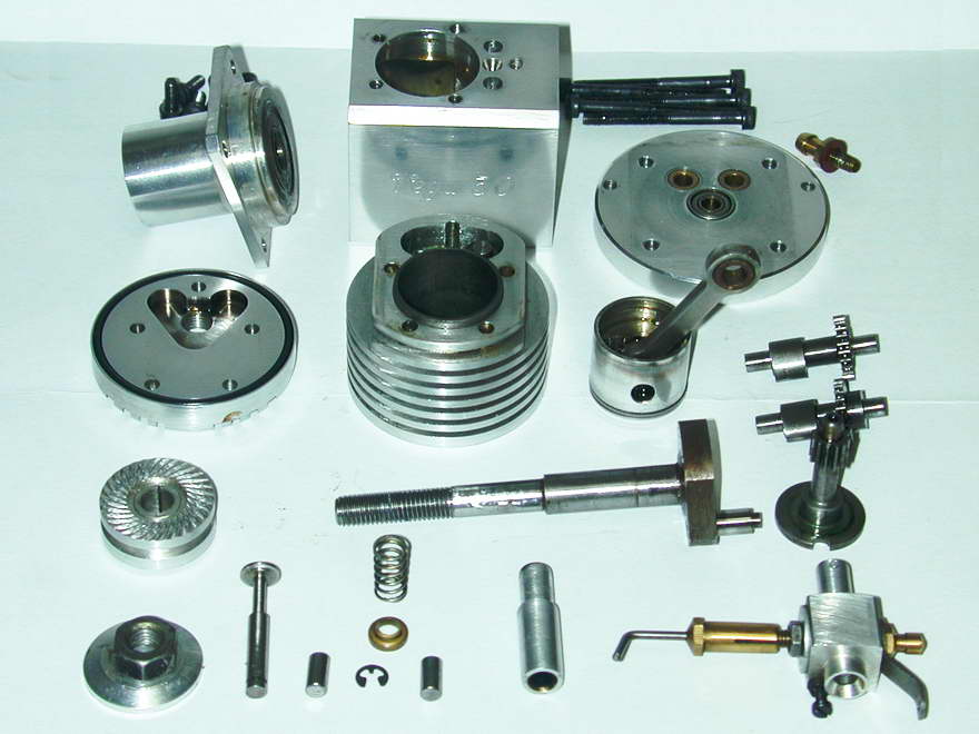 Twin camshafts are used, arranged so that the gears overlap (ie, they are staggered fore-aft) which makes for lateral compactness at the expense of a little extra length. These shafts ride in oilite bushes pressed into the backplate, but run unbushed in the central partition where they are most heavily loaded. The cams are positioned to sit side by side to actuate twin, solid tappets, the latter being 4mm x 8mm solid steel rollers. The rear section of the case carries a screwed in breather tube. The lubrication system is open to interpretation. What looks like a countersunk hole between the tappets could allow oil leaking past the valve stems to drain into the grarcase. Generous holes connect the gearcase with the main crankcase cavity. On the other hand, lubrication blow-by from the ring could pass in the other direction. Doubtless, one or the other does the job and no trapped pockets exist.
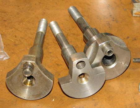
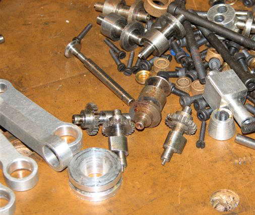 The crankshaft, which was counterbalanced in the usual way, featured a pressed-in crankpin made from a 5mm roller which ride in an oilite bushing in the big end of the conrod. The cams on the other hand are machined entirely from the solid, including the gears (48DP), as can be seen from the blanks in this photo of bits obtained from the "receiver" of the Vega project by Eric Offen. The cams appear to have been formed using a polygon box tool. The camshaft journals are very well finished—possibly ground—then nitrided. Very high quality for what was essentially a hand-made engine.
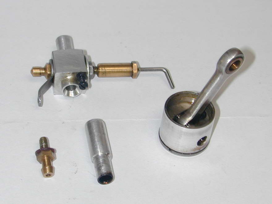
The aluminium piston is turned from bar-stock and fitted with a single compression ring. It runs in a cast iron liner that is positioned off-center in a turned alloy cooling jacket allowing the valves to be fully contained in the aft portion. The valve spring caps are retained by circlips and there is no provision for tappet clearance adjustment apart from the length of the tappets and the valve stems themselves, coupled with the deck and cylinder jacket heights. Given the highly compact assembly the design requires, I can see no practical alternative, although this would require very close attention to dimensions, further adding to the cost of manufacture. It also means that the tappets act against the bare ends of the valve stems which is not exactly ideal. As is normal in small four-strokes, the valves seat on the aluminum cylinder jacket—there are no cages. The exhaust and inlet stubs are secured by grub screws, located to customer request as mentioned earlier.
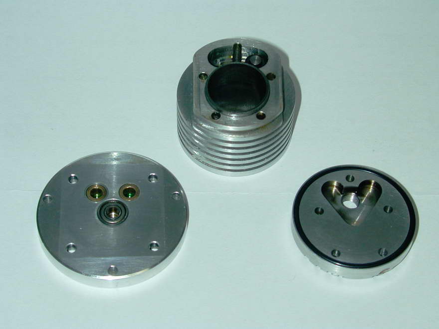
The head has a Ricardo-style chamber. In a departure from convention, the glow plug is located midway between inlet and exhaust. Normal side-valve practice would place it at the coolest point, over the inlet valve. The head and cylinder assembly are secured to the crankcase by five long cap head screws. In place of a gasket, the Vega uses what appears to be a conventional rather than high-temperature 'O' ring. The R/C carburettor is conventional, being a third-party unit.
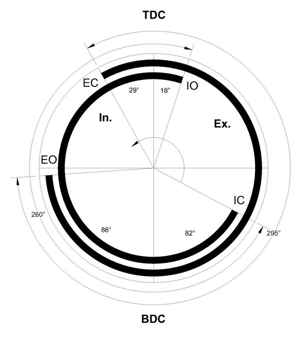 The valve event timing of the sample (serial number 016) was checked using a degree wheel and plunger type dial indicator. The results, rendered in an ETW style timing diagram seen here, show a rather early exhaust opening and a late-ish inlet close, but they are not awful. There is evidence that the tappets are too small in diameter for the cam profile as there is a distinct "click" as each cam passes the fully open position, caused by the tappet suddenly slapping down onto the cam flank—a clear indication that tangential contact is not being maintained. A purist would condem this as limiting top speed due to slap induced valve bounce. But being a side-valve, I somehow think this is not going to be a great problem.
As a final comment on the valve train, recall that the gear teeth are cut direct into the three shafts. They are 48DP with 12 teeth on the crankshaft follower and 24 on the camshafts. This means that the smallest incremental shift that can be made by sliping a tooth one way or the other is 15°. This is a big change, timing wise, so there is really only one way the parts can be assembled for sane valve timing. More significant, the teeth have to be cut very precisely in relation to the cam lobes, adding yet more effort and expense to manufacture.
Conclusion
As well as the OHV prototypes already mentioned, John's experimental types included a .91 glow/diesel side-valve (yes, on the same engine!), and timing belt driven OHV single and four cylinder in-line engines [3]. The Goodall article referenced in the Introduction states that the Vega series were CNC. This is at odds with the description of a "work shop" visit in reference [3] and other sources which name the equipment as Colchester capstain and Myford lathes. If anything this makes the number produced, relitively small as it is, all the more remarkable.In reference [1], Goodall also says that the Vega side-valve engines, although quiet, gained a reputation for being not very powerful—not an uncommon trait for the type. This would certainly be the case if the engines were compared with Neil Tidy's Laser series. Both are British, bar-stock, four-strokes, though the Lasers are all OHV and CNC produced, so comparison with the hand-made, side valve Vegas is not really valid.
A search through all the British model magazines spanning five years from 1988 found only a single reference to the Vegas, and that was peripheral, showing a magneto attached to one by a third party. Although John Harbone did not advertise the range widely, he did run a booth at the 1989 British NATS where he distributed flyers and demonstrated the Vegas[4]. As the engines were essentially hand-made by him alone*, this limited promotion, plus word of mouth, apparently provided all the business he could handle.
My rather subjective impression is that the Vegas have a distinct "amateur" look due to the very simple outward appearance, coupled with square section crankcase and bulkhead mounting disk. The Lasers on the other hand—unfair comparison though it may be—have conventional beam mounts and look more "pro". To really appreciate the Vega, it needs to be pulled apart and viewed with an engineer's eye. This shows a well thought out and very well made engine. That it would be no power-house is undeniable; no side-valve engine is. But that was not the designer's objective, so it should not be the basis for criticism. It is unfortunate that the designer chose, or was forced to sell the design rights. This is an engine that could be built easily in a modest home-shop and would be a delight to the builder. And even if it is no power-house, the skin on the rice pudding would probably come out second-best.
References:
| [1] | Goodall, J: Vega 61 O.H.V. Four Stroke Glow Engine, Model Engine World, Volume 4, Issue 10, Number 46, Feb 1998, p3. |
| [2] | Goodall, J: Readers Engines, Model Engine World, Volume 5, Issue 10, Number 58, Feb 1999, p24. |
| [3] | Imrie, D: Vega Engines and Other Things, Model Engine World, Issue 76, Feb 2004, p22 (editor, Andrew Nahum). |
| [4] | From conversation with David Owen and inspection of the Vega flyers for the .61 and .91 obtained by him at the UK NATS held in August, 1989. |
Footnote
* For a brief period towards the end of production, an arrangement was made with a third party to manufacture Vegas using CNC. The arrangement was quickly terminated due to severe quality issues and un-approved modifications, but not before examples of the 61 and 91, now known as "Andy" engines, were distributed. All these have serial numbers greater than 100 (the Harbone engines have sequential serial numbers starting at one). Some were ok, but others performed so badly they had to be replaced free of charge with "genuine" Vegas. Apart from the serial numbers, the CNC engines can be instantly identified by the curved inlet and exhaust pipes. Collectors should take note and be aware that these engines are of lower value in comparison to the hand crafted engines.
![]()
