MK 17
| Name | MK 17 | Designer | V Petukov |
| Type | Compression Ingition | Capacity | 1.5cc |
| Production run | Lots | Country of Origin | Russia |
| Photo by | Ron C | Year of manufacture | 1959? |
Notes:
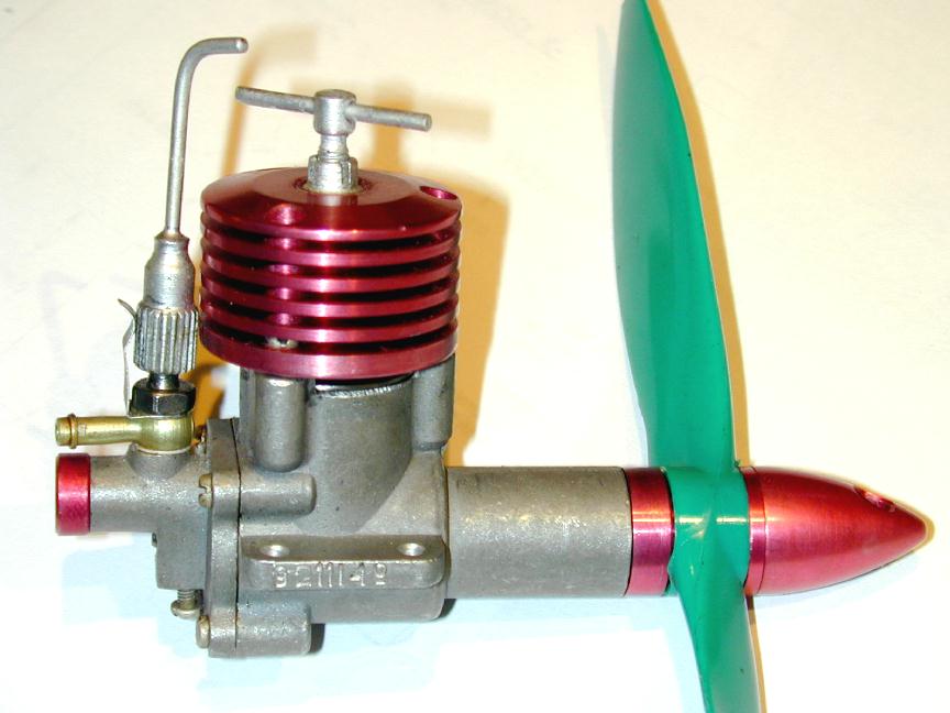
This inexpensive little rear rotary valve induction, twin ball race "diesel" seems to have been around since "forever". There must have been warehouses full of them someplace in the old USSR as they can still be had "new in box" for a virtual song. What is in the box, if you get one, varies. In the best case, the "box" is a fitted plastic container and you'll get the engine, a spanner, plastic propeller, prop nut tommy bar, replacement venturi insert, and mounting screws. In the worst case, you get the bare engine, and a paper bag if you're lucky!
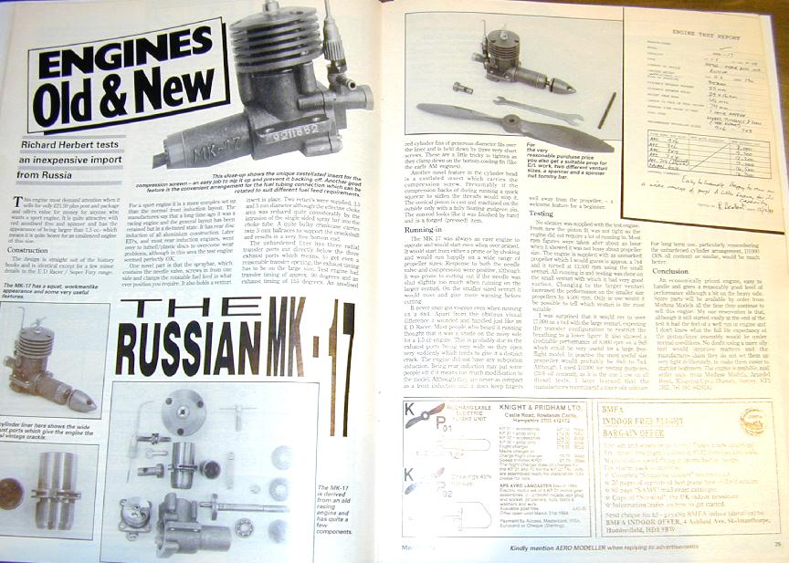 The Mk 17 was tested by the Aeromodeller in the regular column, "Engines Old and New" of March, 1994 [1]. Written by Richard Herbert, the review was generally positive, although it did contain some less than flattering observations. Up until reading this review in preparation for composing this page, I harbored a totally fond regard towards the Mk 17. This was based on the one in my collection (un-run) and the example owned by my flying buddy which we'd run one fine Sunday just for the hell of it. We'd both been most favourably impressed by its performance. Having now disassembled my own, I find myself agreeing with Richard Herbert--so much that I feared this page would verge on plaugerism! Richard concluded that the engine was "..easy to handle and gives a reasonably good level of performance although a bit on the heavy side." However, he'd started out by saying that he felt he was conducting a review of an engine straight out of the 50's. A bit unkind, I thought; then I pulled down my own to take pictures and was driven back to the library to scan magazines for a dimly remembered, earlier reference to the Mk 17. Fortunately I found more than one, and how right Mr Herbert's off-hand comment proved to be.
 The first hit comes from Peter Chinn's column in the February 1976 issue [2]. Here Peter notes that the Mk 17 is a development of the Mk 16K, and that the latter was designed by one V Petukov, "..as long ago..." as 1956 (so Mr Herbert was quite correct in this impressions). The differences noted by Chinn from this earlier engine include beefing-up of case casting, cylinder liner, cooling fin muff, and the removal of three circumfrential oil grooves previously turned in the piston skirt, two above and one below the wrist pin. He also notes that the 16K was first imported into the UK in 1973. He states that the claimed power output from the Mk 17 was 0.14 bhp at 14,000 rpm.
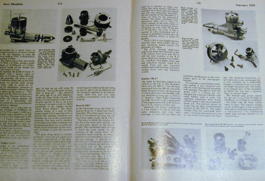
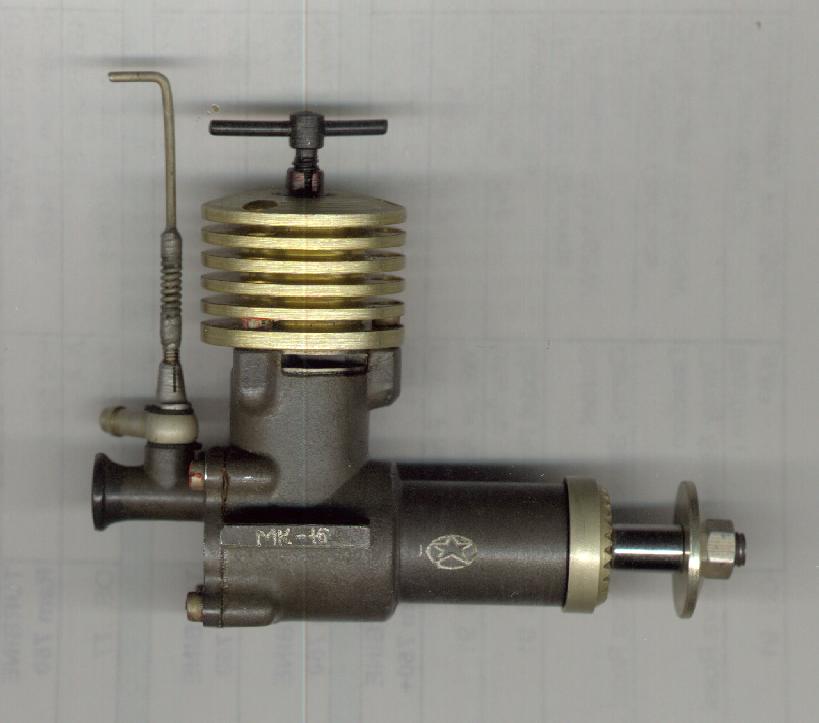
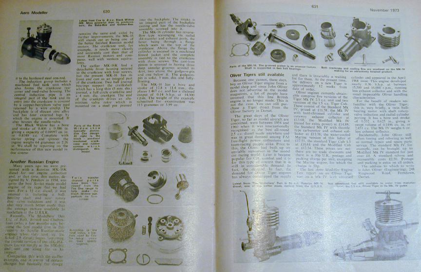 So digging further back to the Aeromodeller of November 1973, we again find Peter Chinn describing an old friend, but closer examination shows not a Mk 17, but the predecessor Mk 16K [3]. Here he again attributes the design to V Petukov, giving 1954 as the year and saying the Mk 16 is "..quite the best Soviet engine of its type that we've seen.". The photos show an engine almost identical to the later Mk 17 with a few less obvious external differences. There is no venturi insert and the rotor pin is permanently rivited to the backplate. The raised lettering on the crankcase journal says "MK-16" (naturally), and is on the right hand side of the case. Finally, the cooling fins have two curions scallops cut on either side of the front cylinder attachment screw. This feature is not symetrical--there is no such relief cut between the rear screws. Internally, the engine appears the same except for the oil grooves cut into the piston. Measurement would disclose many differences though. Although the bore and stroke are the same, the Mk 16K (known simply as the Mk 16) weighed in at 113 grammes compared to 131 measured by Chinn for the Mk 17 (and 130 as measured by me). The power output was quoted (though not tested) as 0.14 bhp at 14,000 rpm, the same as later claimed for the Mk 17, so the 16 would have the edge in the power to weight stakes.
Casting the digital doo-dadds over my Mk 17, we find first that it weighs 130 gm. Heavy. A Mk II Oliver Tiger Cub weighs 114g, and an Elfn 149 is a mere 74 gm. But then the Mk 17 and the Cub are twin ball-race, while the Elfin has no shaft bearing beside the crankcase. Next, it's Russian, right? So we can expect it to be a metric design. But the piston measured 12.72mm. That's 0.501" near as damn--looks like we've got an imperial engine! My Imperial plunger DTI gave the stroke as 0.442". That's 11.22mm. Neither makes much design sense. 0.442" is not close to any standard fraction, and 11.22mm is just plain wierd. Doing the math gives a capacity of 1.427cc or 0.087cuin. Neither is all that logical. Check the screw threads. These certainly matched the metric thread gauges in pitch, but the diameters are a bit unusual. The comp screw measures 3.82mm with a 0.7 metric pitch. That could be an undersize ISO Coarse 4.0 M.7. The head and backplate screws are about 2.44mm diameter, with a 0.45 pitch. This could be an undersize 2.5 M.45 which is a standard size. The threaded portion of the prop shaft is 4.8mm with a 0.8 pitch. An undersize (again!) 5 M.8? But 4.8mm converted to imperial is 0.188", which is 3/16", while .8mm pitch is very close to 32 TPI, and sure 'nuf, a 10-32 nut screws on with no trouble! I give up; and I'll have another word to say about the screws before we're done too...
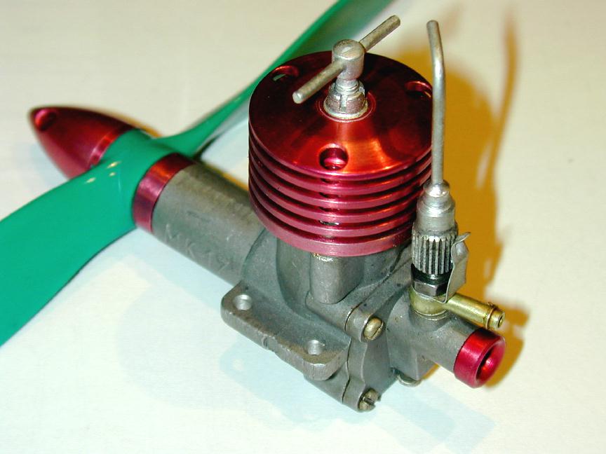
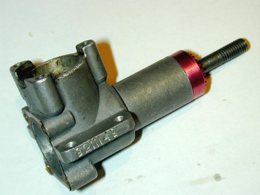 The Mk 17 case is die cast aluminium with a lightly blasted finish. Mold flashings on the centerline die joins and the exhaust area top have been rather crudly dressed apparently against a rather coarse grinding wheel, although the blasting tends to hide this. A serial number is stamped into the end of the right mounting lug (viewed from the rear); while a prominent "MK-17" appears in raised lettering, cast into the left side of the main shaft journal. The journal appears "normal" until you remember this is a twin ball race design. The designer achieved this by using a spindly 6mm shaft, resulting in small bearings and a casting that would not look out of place on a plain bearing motor. The journal length is above average length, permitting the engine to be nicely cowled, but perhaps rendering it a bit vulnerable to violent encounters with terra firma.
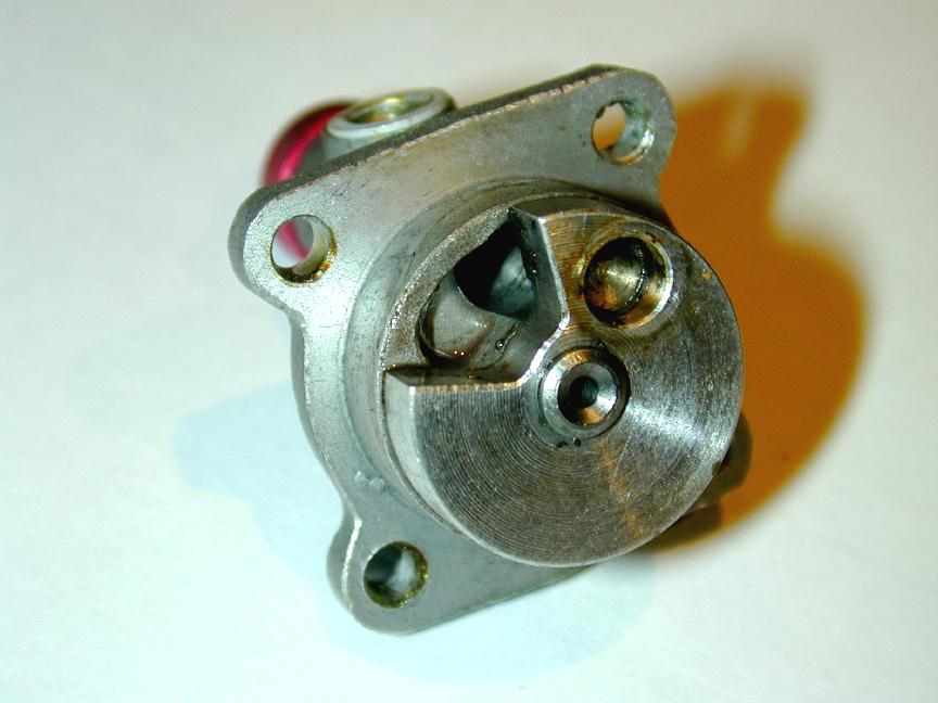
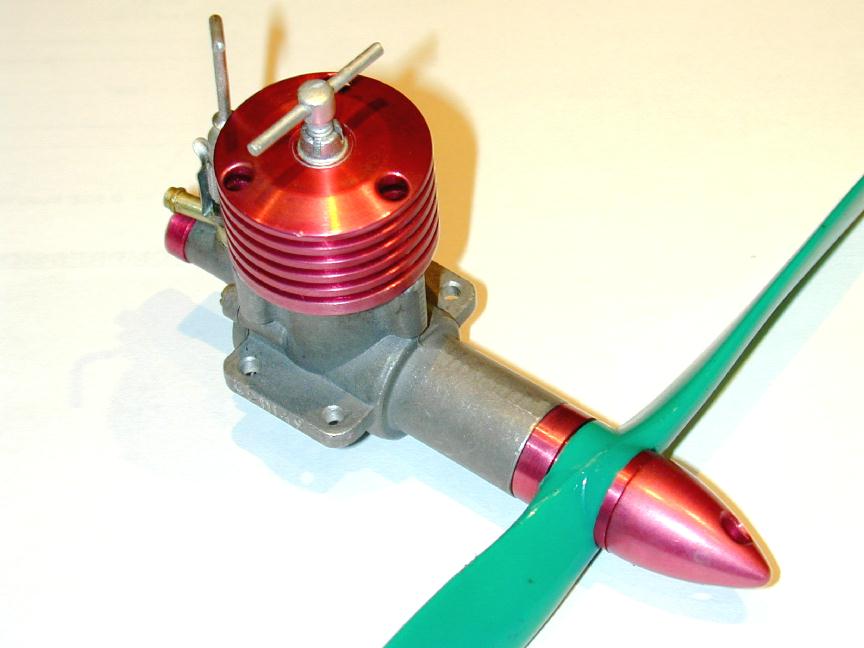
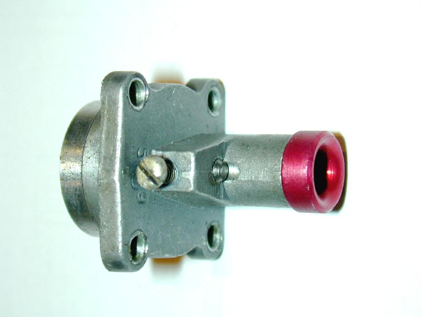 The backplate is relatively conventional with an aluminium timing rotor, held captive under a steel retainer. This retainer is secured by an external screw as shown in the picture here. The inlet is positioned at 12 o'clock, requiring a channel to be provided, following in the direction of rotation, to extend the induction period. I discovered this trick while making the RRV AHC with inlet in the same location. It is not possible to totally govern the inlet duration with the cut-out in the rotor, as the required position would intersect the driving pin position. The relieved backplate trick side-steps that. Note that the backplate is fitted with an anodized venturi insert. The engine reviewed by Herbert was provided with two: 5.0mm, and 3.5mm. Alas, mine came only with the 5.0mm insert. You can also see more numbers stamped under the rotor pin screw. On my engine, this is "539" with the "3" about twice the height of the other two digits. With no evidence whatsoever, I'm going to assert this means the engine was assembled in the March run of 1959. Prove me wrong
  .
.
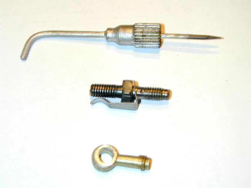 Completing the back-end of the engine, we have the slightly unconventional needle valve assembly. This comprises a piece of hex steel, turned down on either end and threaded. One end carries the needle valve; the other screws into the backplate casting. When tightened up, it protrudes roughly half way into the inlet and locks down the needle ratchet clicker and the fuel banjo, as well as holding the venturi insert in place. The banjo fitting is a nice touch, normally confined to more expensive engines. But closer examination shows some cost savings that are either crude, or smart, depending on your philosophical point of view. The spray bar is drilled through diameterically, not for fuel delivery but for fuel pick-up. Delivery is from a fine jet in the end. The needle seats neatly on the small, just protruding slightly when fully closed. The hole in the banjo is is 4.3mm; the OD of the spray bar at the jet holes is 2.4mm. So we have a lot of slack. Two thin aluminium washers placed on either side of the banjo form a fuel collection cavity in the area where the spray-bar holes reside. Although it's most unlikely that spray-bar will be centered in this cavity, with two jet holes, there is no way to tighten everything up that won't feed fuel--though some will be better than others. The needle is a bit massive. Hell, the whole thing is a bit massive, but it's innovative and functional. Overall, I gotta say I like it.
 The cylinder liner is probably what got Richard Herbert feeling he'd stepped back into the 50's. It's almost pure Allen-Mercury. The liner is steel which Herbert asserts to be unhardened. I certainly had no difficulty scribing a mark on it to assist reassembly in the same orientation. It locates in the crankcase on the exhaust belt which is a close fit inside the three head screw pillars cast into the case (just like the A-Ms). It seals (with no gasket) on the narrow area under the exhaust band and the top rim of the case. Underneath the three exhaust ports are three transfer ports. The diameter of the lower portion of the cylinder where these are cut is smaller than the bore in the case, so we achieve 360 degree transfer, just like the AMs and EDs of the 50's. The downside is that the cylinder is not strongly supported, and the exhaust is fully open before transfer opens. So transfer duration is comparitively small and scavenging, despite the conical piston top, is not too efficient. Notice finally how the bottom skirt of the liner is chamfered to assist gas flow up into the transfer belt.
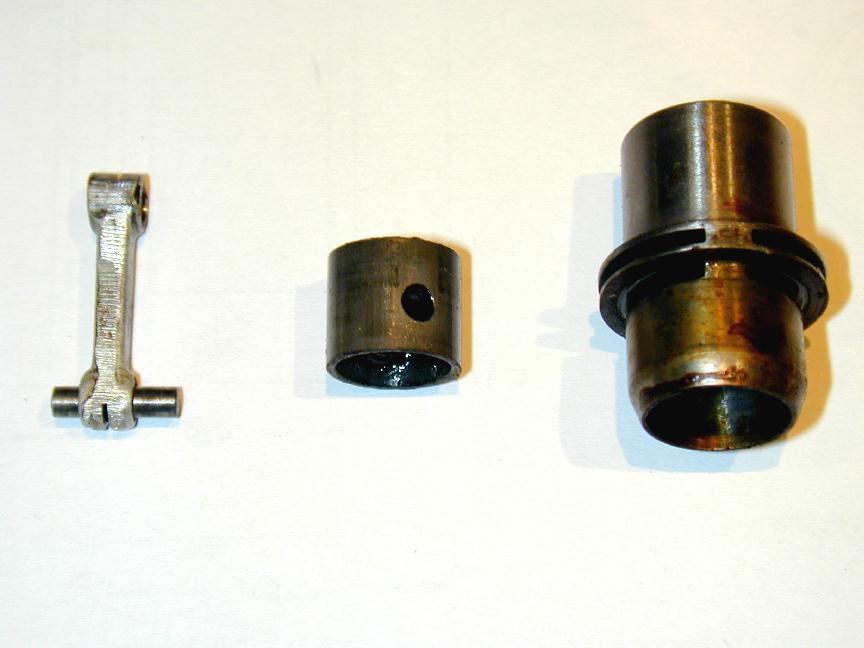
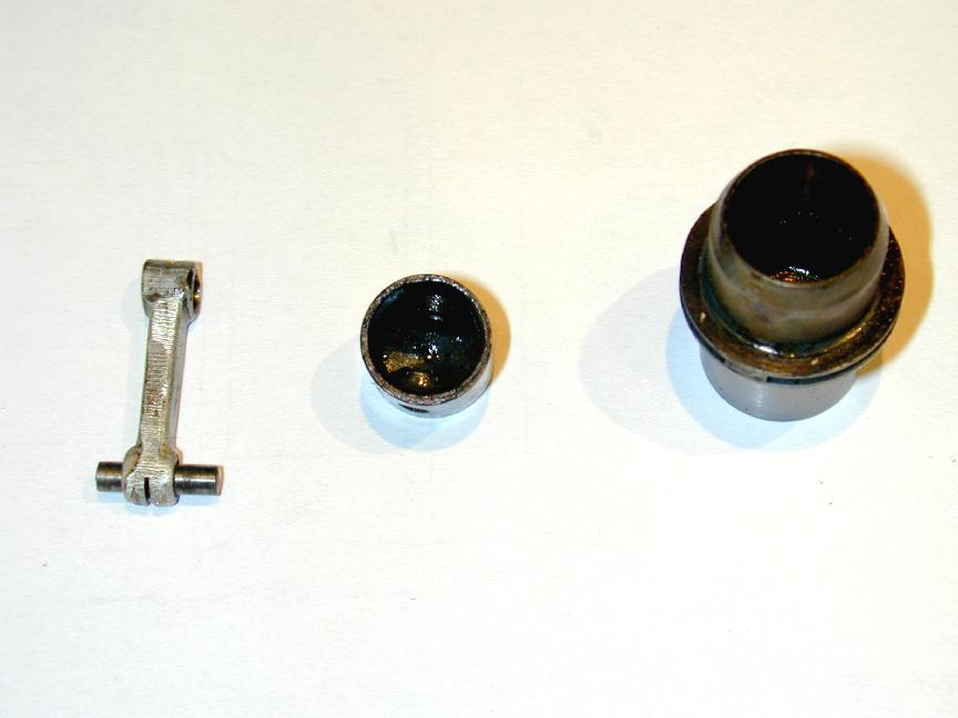 The piston appears to be cast iron. Not turned from cast iron, but actually cast, with little wrist pin pads and generously hollowed. As mentioned above, it has a conical top, and the contra-piston has a corresponding conical depression. The wrist pin is fully floating with rounded ends. The conrod appears to be forged aluminium, very, very crudely de-flashed on the sides, but with narrow oil slits cut into both ends--just like motors intended for high speed running. I read (in White's R2800 book) that forging aluminium can increase the material strength by up to 50%. This engine is just loaded with contradictions, or perhaps it's a case of care and vision on the part of the designer, let down by the assemblers. By the way, the example photographed here is new, "unrun", never mounted, no question. But it shows sighs of having had fuel in it, and there are feint wear marks where the floating wrist pin contacts the liner. I'd have to say this indicates factory running--in fact I had to use heat to free the piston up for disassembly. Another aspect that says "quality" despite the lack of same in other areas (and wait for the doozy at the end).
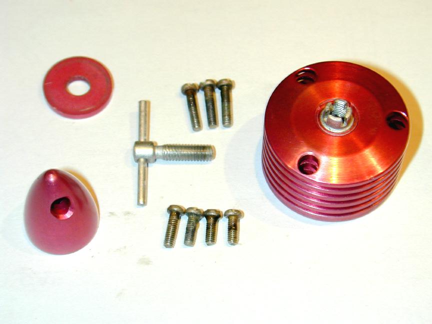 The remaining parts are shown here. The cooling fins are conventional, anodized aluminium, but in another touch that screams attention to detail, the compression screw does not thread into the head. Rather, the head carries a plated steel insert, "castelated" to exert some pressure (adjustable) on the screw thread. Although apparently pressed in place, a flange on the bottom of the insert will ensure it stays in place. The spinner nut and washer are also anodized to match. Now look at the screws: three long ones for the head and four short ones for the backplate. The screw holes in the cooling fins clear the screw heads all the way down to the last, thick fin. This is nice. The head screws need only be short and so less prone to suffer from torquing them up. The backplate screws (same thread) are unusual for their lengths; no two are the same! They have not been cut, that's just the way they are.
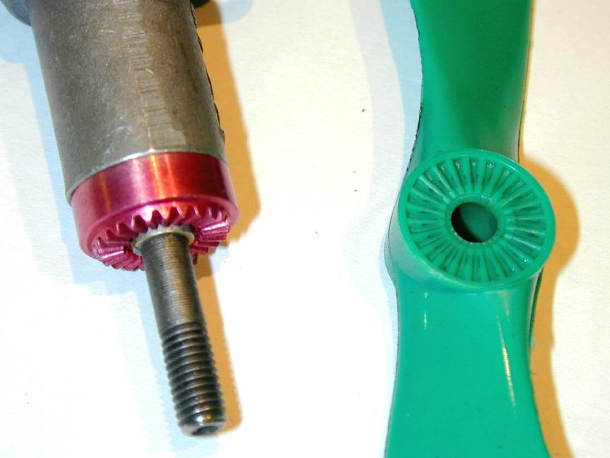 I think one of the nicest features of the Mk 17 is the knurling on the prop drive washer, the corresponding spline molded into the prop, and the way spinner, prop, prop-driver and crankcase journal all neatly match and flow into one streamlined shape. The splines exactly match the knurling. This engine will flick over without sliping with the spinner nut only finger tight. And that knurling job! Normal practice is to plunge knurl by mashing a knurling wheel into the face of the driver disk. A moment's though will tell you that you are applying a speed gradient across the knurl wheel, effectively asking the knurl face on the outside to turn faster than the side on the inside of the driver. Guess what? It can't. So unless special tooling is used (like on Elf engines), the knurl has to slip a gear or two and the pattern produced gets trashed, to some varying degree. You can angle the knurl face to minimise this, but that shows, as does skipping. The Mk 17 knurl (pardon while I rave a bit more) is sodding-well perfect. The inside depth is the same as the outside. It's like it was cut as a little bevel gear, except with no bevel! I'll stop now and just say it's locked to the splindly crank shaft with a tapered collet.
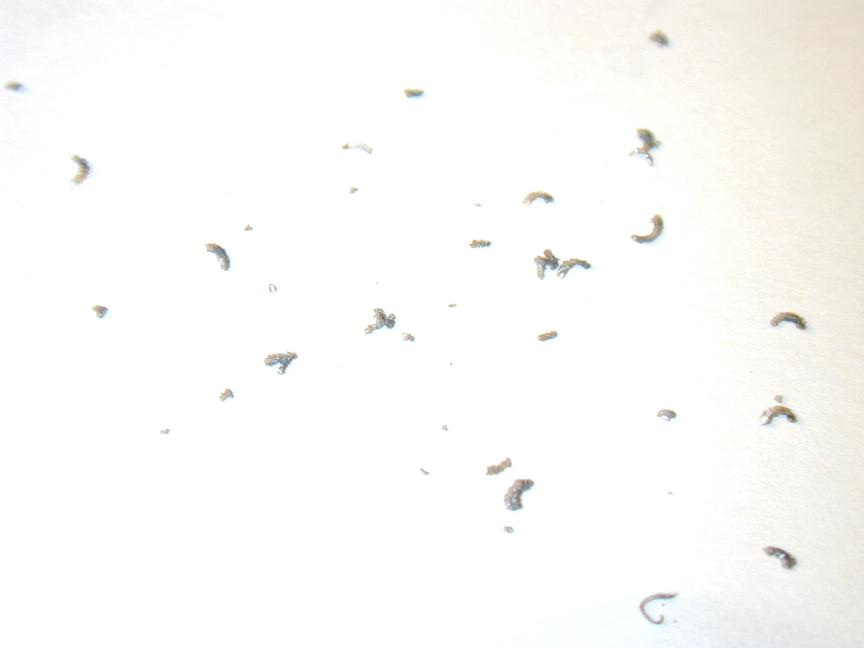 Having now raved on enough about the astounding quality of the knurl, and other neat features, gettaloadathis: you are looking at swarf. Oodels of swarf. I just tapped the stripped-down case over a piece of paper and out it poured. Admitadly, it was trapped in the blind, tapped holes of the cylinder hold-down screws and backplate threads, but it's obvious that there was no attempt made to clean out the case after final machining operations. Talk about contradictions. I didn't pop the crankshaft while taking the photos because I don't like needlessly disturbing ball-races, but I think that if I ever decide to run this motor, it's going to get an unlrasonic clean first. All that said, I still like it a lot.
References
| [1] | Herbert R: Engines Old and New, Aeromodeller, Volume 59, issue 698, March 1994, Nexus Special Interest Publications Ltd, p24. |
| [2] | Chinn P: Latest Engine News, Aeromodeller, Volume XXXVII, No 454, February 1976, Model & Allied Publications Ltd, p63. |
| [3] | Chinn P: Latest Engine News, Aeromodeller, Volume XLI, No 481, November 1973, Model & Allied Publications Ltd, p104. |
![]()