Mills P75 and S75
| Name | P75 and S75 | Designer | unknown |
| Type | Compression Ignition | Capacity | 0.73cc |
| Production run | lots | Country of Origin | England |
| Photo by | Bert Striegler, Ron C | Year of manufacture | 1948-64 |
Background
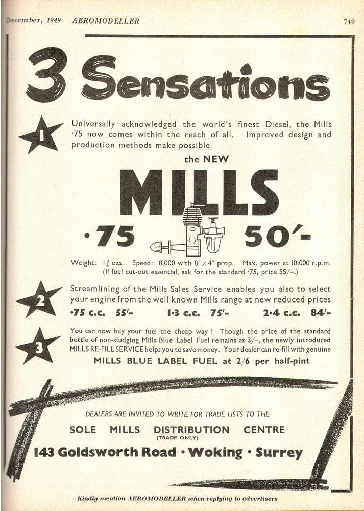
Many reviewers have nominated the Mills .75 as the greatest and most popular, all round sport engine to come out of England of all time. Based on it's reliability, together with its simplicity, performance, and ease of operation, I don't think I'd want to argue with that. Manufactured by Mills Brothers (Model Engineers) Limited of Woking, the "point seven-five" and larger, but short lived Mk III 2.4 both appeared in 1948, about two years after the release of the highly popular Mills 1.3 Mk I. A year later, Mills revised construction (presumably, shifting to a cast crankcase [1]) and introduced a second model at a slightly lower price.
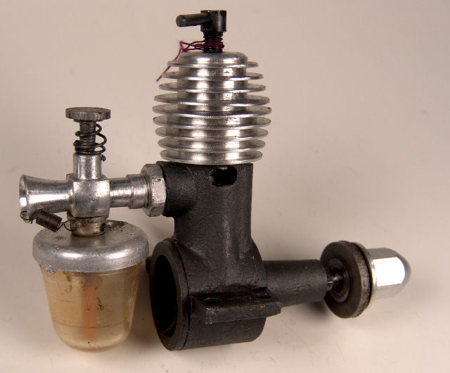
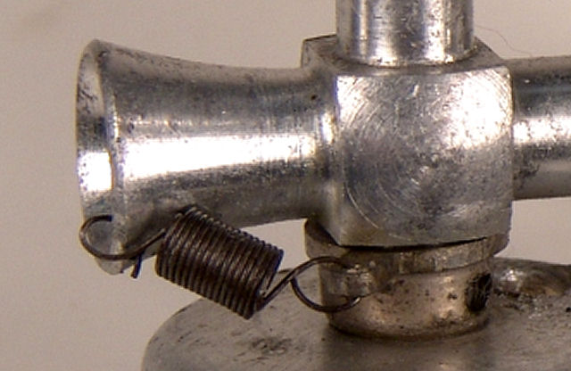 The two versions of Mills .75 were differentiated by the prefix "S" (for "Standard") and "P" (for "Popular"). The S75 was fitted with a spring loaded air-bleed cut-out arm similar in operation to that fitted to the larger 1.3 and early ED engines. The P75 was identical, but had no cut-out fitted. As seen here, the cut-out arm is spring loaded to the cut position. In operation, a line to a timer would hold it against spring tension until released. Notice the small hole used to secure the spring—we'll mention this again at the end of this page.
Construction
 The .75 closely followed the practices established for the 1.3 Mills. A hardened nickel steel shaft ran in a bronze bushing, pressed into a magnesium crankcase. Reference [1] states that early .75 cases were machined from solid magnesium. This was later replaced with a gravity cast magnesium crankcase, of which, only the front bearing housing was machined. All cases were treated with a chromate anti-corrosion process that produced a characteristic black finish—not anodized as some references state (though some Mills 1.3 backplates were black anodized). The tool-steel piston ran in a "Nitralloy" chromium-molybdenum liner (both hardened and ground, naturally). The connecting rod was a high tensile aluminium alloy of circular cross section. The steel prop driver was anchored by two flats on the shaft, giving the floppy-driver look when not cinched up by a prop, as seen in our heading photo. The venturi was turned from aluminium alloy, fitted with a stamped tank top into which snapped a clear plastic tank. This arrangement worked adequately until a model landed in long grass, at which time the tank would immediately detach itself and hide.
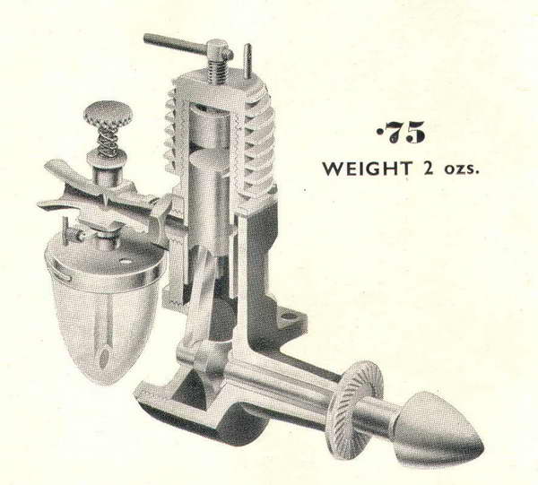
The liner was a simple turning with opposed exhaust port slots and two pairs of holes fore and aft for transfer and inlet ports respectively. This design gave solid metal between the port openings and allowed the wrist pin to be fully floating with no danger of jamming in any port opening. The skirt of the liner had transverse slots to accommodate conrod travel and simply dropped into the crankcase. The later being threaded 26 TPI for the characteristic "bee-hive" cooling fin head which clamped the liner via its locating flange. All these features should be apparent from the "exploded" picture here—which is of my own replica made from the Classic Model Airplane Engines replica kit—not an original Mills, and has some differences to the construction just described.
The engine weighed a mere 1-3/4 ounces bare, with a bore of 0.330", and a stroke of 0.520". This classifies it as a long-stroke, side-port design. Using those figures, my HP calculator says that the capacity is 0.04447 etc cuin, or 0.729cc, close enough. Various engine reviews are able to agree on the bore and stroke, while arguing about the displacement—probably meaning their micrometers were similar, but the length of the slide rules used to do the math differed. In comparison, this is the same weight as a Cox Baby-Bee of 0.0494 cuin. Not bad for a compression ignition engine, and just try to spin a 9" prop with a Baby-Bee!
Operation and Imitation
The immediate success of the .75 was arguably due to it being the right product at the right time. People were "air-minded" and aeromodelling had a large following supported by a vibrant special interest press publishing endless designs suitable for it. Flying fields were plentiful and noise complaints unheard of . In this climate, a small motor that started instantly, even in the hands of a complete novice, and could be adjusted to a wide range of rpm with small or large propellers was a perfect choice for beginners and experts alike. Mills exported to all parts of the fading British Commonwealth, with a few even finding their way to the US—although the general rejection of "diesels" as "oily and smelly" there meant they gained no popularity.
In 1960, Mill Brothers (Model Engineers) Ltd was acquired by the Aling Industries Group. Although they stated an intention to continue production and even expand the model engine range, production ceased in 1964 so they could concentrate capacity on the more lucrative aviation market [1], an event that Peter Chinn describes as "...nothing short of a national disaster by those who had come to regard the .75 as almost indispensable to the survival of the hobby".
The void left by the demise of the Mills was filled, to a degree, in later years by the K75 by Aurora of Calcutta, India. This version was produced from tooling officially acquired from Ailing by Mr Suresh Kumar. Kumar, a businessman, manufacturer and modelling enthusiast, also acquired rights and parts inventory for the defunct AM series and the Taplin Twin. The K75 differed from the "real" Mills in having a sand-blasted, aluminium case, though still with a taper turned journal like the magnesium case versions. The shaft however was made from some sort of toffy-like steel which bent freely even on smooth landings. Fortunately, it was so soft that it bent back just as easily. The venturi, while looking the same, was fabricated by screwing a remarkably coarse threaded vertical part into the inlet, then drilling through. The tank top pressing retained the bowl by bending over two thin tabs and pity help anyone who needed to unbend them—these are one-shot tabs. Still, the K75 retained the easy starting and operating characteristics of the original and served as an adequate stop-gap to the next revival.
This came in the form of two other notable replicas from Australia and England. The first was a labour of love by Ivor F. The second came from the English engine manufacturer, Irvine Ltd. Quality on both of these engines is exceptional. Irvine solved the runaway tank by making it a screw fit into the top. Ivor's replicas (called the "Doonside Mills" after his home suburb), reintroduced a feature of the original, fully machined version of the engine by using a simple spring wire "C" clip that will appear on the Classic Engines reproduction plans (refer to the cut-away drawing by FA Hunt, above).
Well worth noting is the extreme danger presented by the cylinder liner rotating as the head is tightened down. The 1/8" diameter conrod is swinging in two 5/32" slots milled in the skirt of the liner. Unless the liner is a tight press fit in the case, it is apt to rotate a bit on assembly as the head is screwed down. If this happens, the rod will rub in the slots. Bad for the rod and bad for power loss. Worse, if it moves under vibration, the engine can jam solid with painful results (ask me who has had that happen to them...) The Doonside Mills solved this problem by inserting a small pin into the case that registers with a slot in the liner flange. This assures correct alignment and permits the head to be tightened with no fears. Again, the Classic plans will show this modification. The photo shows the pin fitted to my own prototype Classic kit built engine, regrettably after having disaster scenario #2 occur. This is a bullet proof mod that is easy to do with a Dremel cut-off wheel to cut the slot. After setting the alignment, the slot itself is used as a guide for a #68 drill. To complete the modification, a short pin made from 1/32" piano wire is then pressed into the hole so its top is just below the top of the liner flange.
Another testament to the popularity of the Mills .75 in all its forms is the number of times it has appeared as an engine review in the aeromodelling press—both English and American. The Engine Review Index lists 14 reviews, even if half of them are by Peter Chinn! Note the inset 3-view of the .75 on this page photograph. It appears to be of the original, fully machined case version—a scaled down Mills 1.3 Mk II in every respect.
The review by Stu Richmond in American magazine Model Builder is worth noting in closing as I believe it has propagated a misconception. The review shows three different issues of the engine: a Near-New-In-Box (NNIB) S75 obtained by Stu from a friend in England, a very limited run replica made by Jiri Patrman of Czechoslovakia, and the then recently released Irvine replica. Stu gives a fair potted history of the engine, adding that his research elicited a letter from Henry J Nichols, noted British aeromodelling pioneer and owner of a very well known London hobby shop which served as one of the first retail outlets for the Mills range. In his letter, Henry J states that the .75 and 1.3 before it "..were designed by a charming Swiss engineer who worked for Mills Engineering...". This reinforces the similar statement by Ron Moulton published in ECJ and the SAM 35 Yearbook (references as given in the Mills 1.3 review). Sadly, neither reference gives the name of the talented designer.
Although he gets the introduction date for the original wrong, Richmond's review notes the replicas by Doonside and Irvine, and makes a statement that I believe to be incorrect, saying: "There's a tiny hole drilled in the flared part of the intake tube, about .010 inch to prevent over-choking the resultant flooding." (no error; I quote verbatim). He adds that some Bantams and Fosters had this feature too [3]. Sorry Stu, your NNIB S75 is missing the bias spring of the cut-out, perhaps because an earlier owner wanted to disable it from the at-rest, activated position. The hole is the aft anchor point for the spring (see photo at the top of the page).
Initially, I was inclined to totally reject his article, even though his reference to the Foster and Bantum indicated that he knew of such a practice, and lacking the spring, had jumped to his conclusion. But a brief reference in Ron Warring's Miniature Aero Motors describes this feature in general—the drawing provided shows the hole as being between the needle and the crankcase rather than on the air inlet side of the needle—but does not state which engines may have employed it. I think that even with this, or a larger hole, it would still be possible to flood through choking, but at least I've been saved from making a complete fool of myself (again) by poo-pooing the concept completely.
References:
| [1] | Chinn, PFG: Motor Miscellany, Radio Modeller, MAP Press, April 1988, p42. |
| [2] | Company Advertising: Aeromodeller, Volume XXX, No xxx, April 1956, Model & Allied Publications Ltd, pXX. |
| [3] | Richmond, S: Engines of the World, Model Builder, RCMB Inc, ISSN 0194 7079, Vol 18, Number 194, March 1988, p26. |
![]()