Morton M42
 |
 |
 |
| Name | Morton M42 | Designer | Bill Morton |
| Bore | 0.625" | Stroke | 0.600" |
| Type | Four-cylinder, four-cycle | Capacity | 0.74 cuin (total) |
| Production run | Zero, nil, none. | Country of Origin | USA |
| Photos by | ECJ & Dietmar Kolb | Year of design | 1944 |
Background
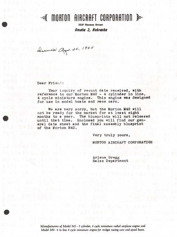
The concept of a four cylinder, in-line four-cycle engine for use in model cars and boats followed logically after the five cylinder radial Morton M5 for aircraft. Work on the M4 started in 1944 under Glen Morton's uncle, Bill Morton. Where practical, he decided that the engine should share components from the M5, like the pistons, wrist pins, carburettor, and ignition system (obviously with a different distributor cap). The engine used a rotary valve that was the cause of problems and the eventual abandonment of the project. No engines were produced, but evidently some preliminary drawings and sand castings "escaped", allowing some amateurs to build examples. Undeterred, work commenced on a second version that utilized a more conventional cam sfaft actuating side valves. The only M5 components used were pistons, ignition harness, and perhaps valves. Although announced to dealers, the engine never reached production, nor were any detailed drawings completed [1]. But examples exist as evidenced by the photos on this page. We'll come to that later.
Description
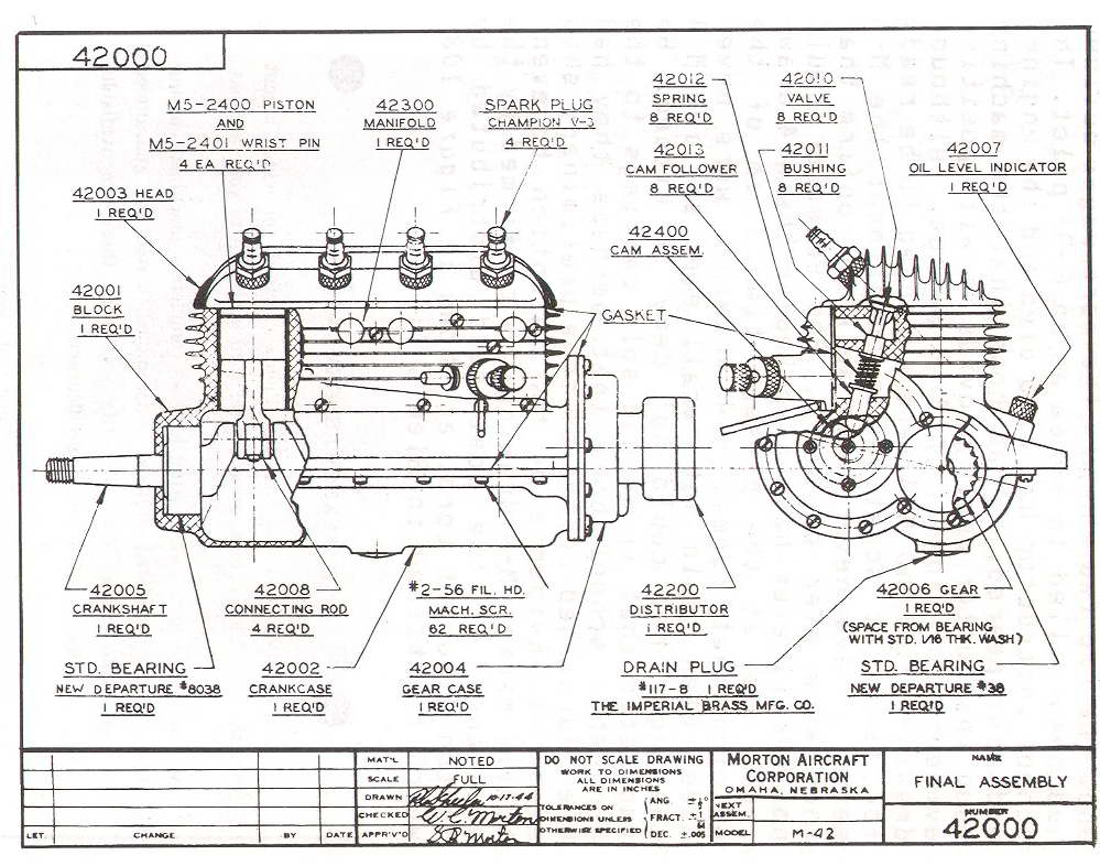 This drawing is the only engineering drawing known to exist; no details of parts, nor any dimensions have ever been found. It shows what at first looks like a straight forward design with a double throw crank supported fore and aft by ball races. The conrods have split big-ends and flat crown pistons. The crankcase is split horizontally along the shaft axis. The other castings are a one-piece cylinder head, gear-case cover, and inlet/exhaust manifold with integral carburettor. Notations credit the drawing to RG Scheeler dated 1944-08-23, revised on 1944-10-17. The drawing was checked by WC Morton (Bill) and approved by GR Morton (Glen).

Now let's consider some of the machining implications of the design as drawn. The front bearing recess is similar to that on the M5 except that it is located deep in the assembled case halves. No detail is shown of where the rear bearing is located, but the flange on the rear of the case argues that it too is machined into the assembled case halves. Both would need to be machined by line-boring from the rear. The bearings called out are different. If their OD sizes are different with the front one smaller, a two point boring bar could be used to provide the correct alignment. And as if that were not bad enough, the front bearing for the camshaft is a blind recess that must be bored longitudinally from the rear, parallel with the crankshaft. This is an operation I would not relish at all!
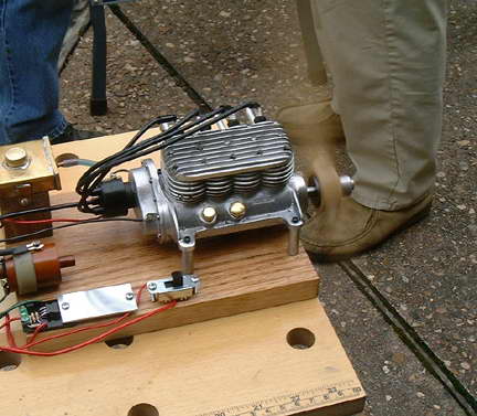
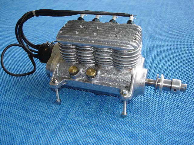
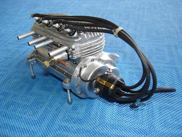
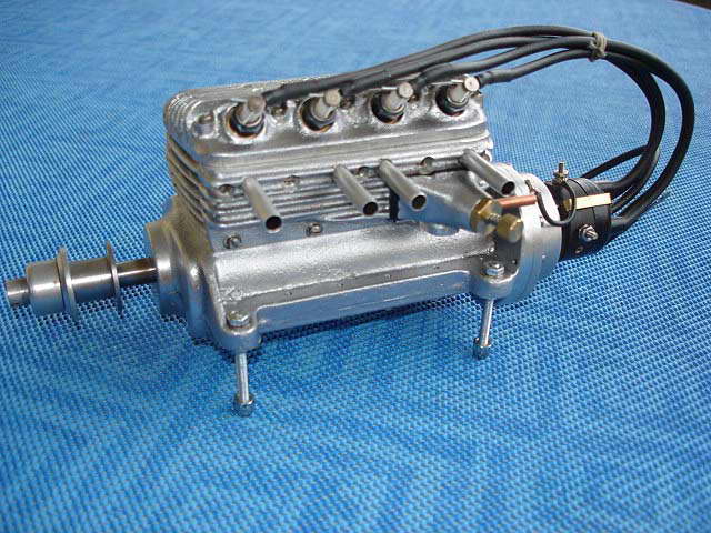
The earlier rotary valve M4 pictured above routed a fuel/oil mix through the crankcase and gearbox for lubrication. The M42, while still specifying a 5:1 petrol/oil mix, appears to have a wet sump. Note that the drawing shows one "42007 Oil Level Indicator". The engine pictured here and at the head of this page appears to also have a centrally located oil filler with a hex head cap. The means by which the original engine was intended to inject air is a bit of a mystery.
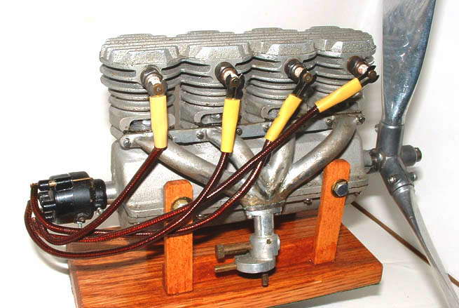
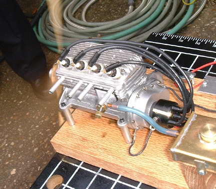 The GA shows a throttle arm on the bottom of the cast-in needle valve boss, but no other openings. The picture shows what may be a separate casting with what may be an updraft inlet. It has no throttle arm, plus the fuel inlet pipe faces aft and looks like a bit of an afterthought. The cut-away on the GA suggests the tappets were splash lubricated, making the coring for the sand cast case very complex unless the liners were not fully supported. Worse, there does not appear to be any way to adjust the tappet clearance, and final assembly of tappets, valve guides, valves, springs and caps would seem to require several tiny gnomes with three arms and six fingers.
M42 Examples
So, the Morton company never released complete drawings and built no prototypes, but M42's exist; how come? One example by noted Morton fanatic—and I use the term in the nicest possible way—Dennis Fadden, appeared on the front cover of SIC. Dennis based his engine on the single GA sheet and sand cast his own parts [2].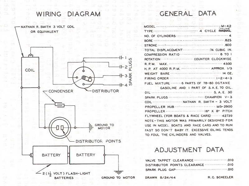
Another example appears in the AMEE with the photo credited to Ward Hallenberg. This engine is very similar to our heading photos, although the carburettor is substantially different. Both are fitted with an M5 style prop hub. Even though it is not stated, this engine is probably one of the engines produced by Jim Hawk, now living in Oklahoma, USA. Again, these engines were "scaled" from the single factory drawing outline and sand cast by the builder. If you do a "fin count", you'll find the engine matches the drawing exactly, even if the profile is not as sharp—the original probably being intended for die casting. Note on the M42 spec sheet how the type is 4 cycle radial with the "radial" crossed out and inline hand-lettered in. Cut-n-paste was alive and well in 1944.
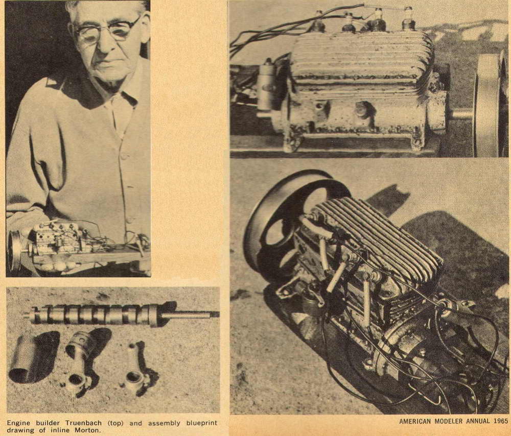
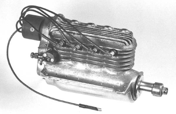
Details of yet another example appeared in the American Modeler Annual for 1965 [4]. This one was built by Mr WT Truenbach of Beaverton, OR (hey! I use to live there!) According to the article, WTT received yet another copy of the 42000 drawing as an unexpected gift with a set of M5 plans he ordered from the Morton company. Although only a hobby machinist, WTT set about producing his own patterns, castings and eventually at least two running M4's—the second from his second-rate casting, the first having being stolen. The photo shows what may be a camshaft fabricated by interspercing cam and bearing segments on a shaft, although it is possible that it was higged down from a single bar. Having the bearing segments larger in diameter than the cams is a practical way of supporting the cam shaft.
Conclusions
 The Morton company never went into production on any of their four cylinder in-line engines and no documented "factory" prototypes are known to exist. This was confirmed by Glen Morton in an interview shortly before his death by Bob Knutson [1]. However, well made examples do exist based on the single factory drawing and specification sheet. It is not fair to call these "knock-offs" as the builders needed to solve many tricky problems, not just copy and existing engine. And neither Dennis Fadden nor Jim Hawk are anything but up-front regarding the nature of their work. But as engines change hands, provenance tends to blur, so I'll say it one more time. There are no factory made in-line Mortons!
 Just to round out the story, there was another M4 designed by the Mortons as a two-stroke. Castings have surfaced from time to time, but no drawings have ever been found, so those completed M4 two-strokes as exist have been interpolated by talented builders [1][3].
References:
| [1] | Knutson, R: The Morton Story Part 8: The Morton Fours, Engine Collectors' Journal, Volume 14, Number 5, Issue 77, October 1984, p1. |
| [2] | Fadden, D: Cover story, Strictly Internal Combustion, Kent WA, Volume 1, Issue 4, Aug/Sep 1988, p2. |
| [3] | Dannels, T: American Model Engine Encyclopedia, Country View Enterprises, USA, 2005, p172. |
| [4] | Nichol, RE: American Modeler Annual 1965, Condé Nast Publications Inc, NY USA, 1965, p56. |
![]()
