Mills Bros 1.3 Mk I
 THIS PAGE UNDER CONSTRUCTION
| Name | Mills Bros 1.3 Mk I | Designer | A L Hardinge |
| Type | Compression Ignition | Capacity | 1.3 cc |
| Production run | 3-6,000 [4] | Country of Origin | England |
| Photo by | Bert Streigler, Roger Schroeder |
Year of manufacture | 1947-49 |
Background
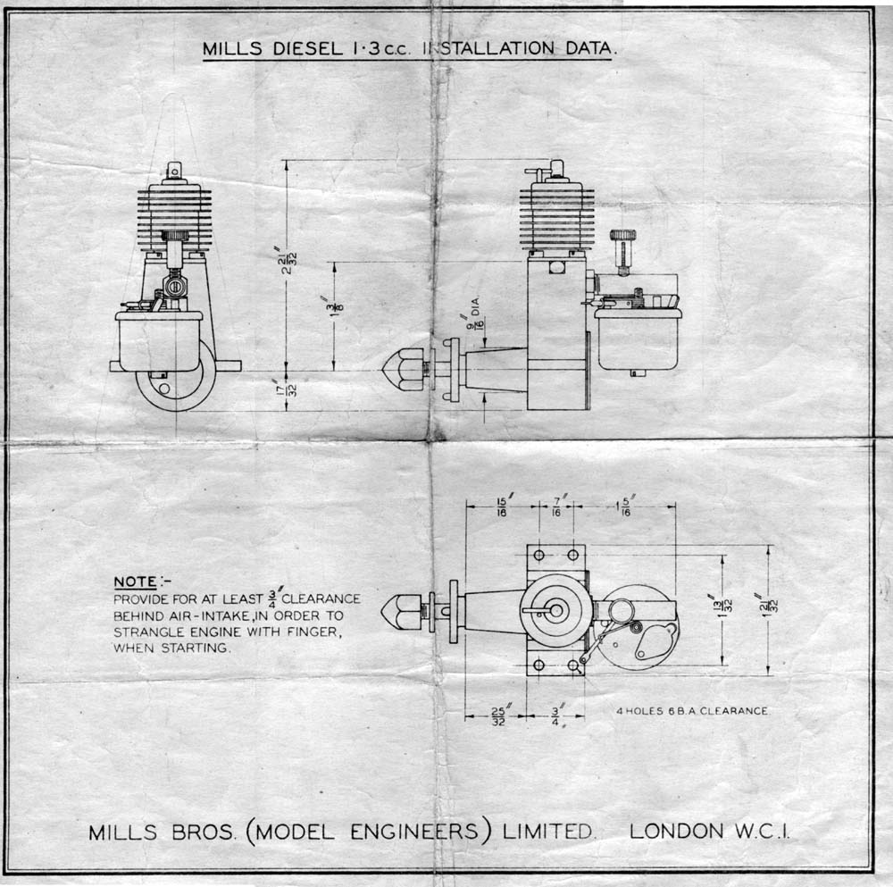
I approach this engine with trepidation, not because of a lack of facts, rather because of the weight of information available and the status of those who have authored it! In fact, we could say this engine has been done to death and anything I can add is of little impact or worth. Nevertheless, the Mills 1.3 strongly deserves an on-line reference, so my small contribution will be to use the Library to collect for the first time a reasonable bibliography of writings on this engine. Of necessity, we'll have to touch on the Mk II version of the engine, but I try to constrain descriptions mostly the aluminum cased Mk I. As a good start, the image here is a scan of the official factory installation drawing that accompanied the first version of the engine (courtesy of Mr Ken Croft, England).
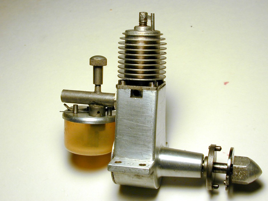
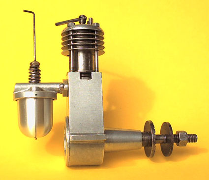
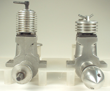
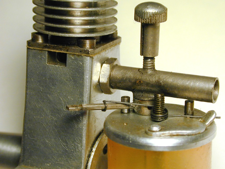 The first version of the Mk I, frequently referred to as the "Mark One, Series One", appeared on the UK market in 1946 [9]. This version is distinguished by a cooling jacket having all fins the same diameter. All Mk I's had aluminum crankcases as seen here. Anecdotal evidence exists that the first engines were "hogged from the solid" [5] although this may mean that rough sand castings were machined all over. The photo here clearly shows the fuel cut-out mechanism. When forced against its stop, the spring loaded arm rotated a hole in the collar attached to it into alignment with a hole in the fuel feed stem. Provided the engine was not running flat out on a small prop, this quite effectively stopped the engine, though not instantly. Lawerence Sparey wrote that beyond a certain RPM figure, the cut-out was likely to have no effect whatever[6]. All the venturi components were brass, plated after soldering. The plating is either cadmium, or dull nickel.
 The most exhaustive treatment of the Mills 1.3 appeared in Roger Schroeder's Engine-uity column in The Engine Collectors Journal [3][4]. Roger's research is augmented by material supplied to him by Ron Moulton, David Owen, and others. Ron's words later appeared in the SAM 35 Yearbook Number 7, enhanced with a transcript of a talk given at Farnborough in 1985 by Mr Reg Elton who had commenced working at the Mills Surrey factory in the spring of 1947. It is from Mr Elton that the "hogged from the solid" assertion derives—on Myford ML 7 lathes no less [5].
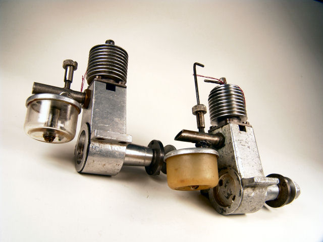
The Mk II 1.3 was introduced in 1948 [9]. It is distinguished by a markedly different case, cast in magnesium, lightened by taper turning below the exhausts, and a die cast aluminum venturi (which together saved an ounce of all up weight). So even though Mk I's are easy to distinguish by their straight sided, aluminum cases and fabricated, plated venturi assemblies, there are subtle differences in the early variants. Most obvious is the change from the straight sided cooling jacket to the "bee-hive" design commonly referred to as the "Series II" (which has been rather discourteously, if accurately described as the "pin-head" model). Less obvious are the changes made to the timing. The ultimate reversion of the engine and timing appeared in 1949 giving a substantial performance improvement [9].
It is generally accepted that the Mills 1.3 owes a lot to European designs. Ron Moulton [5] suggests a connection to the Swiss Dyno, citing Henry J Nichols as having met a Swiss engineer at the Mills factory. Mike Noakes suggests that the engine was essentially an Imperial version of the French Alouchery 1.25 pictured here [2]. This engine was available before the first appearance of the Mills, and a certain family resemblance is unmistakable. The Mk I Mills was not all that Imperial either. The crankshaft was precisely 5mm in diameter, the compression screw thread was unmistakably M4x0.7, the crankshaft nut and cylinder screws were BA (British Association—a metric thread series), while the needle valve thread was 1/8" Whitworth (40 TPI). Altogether, quite a mixture!
|
|
|
|
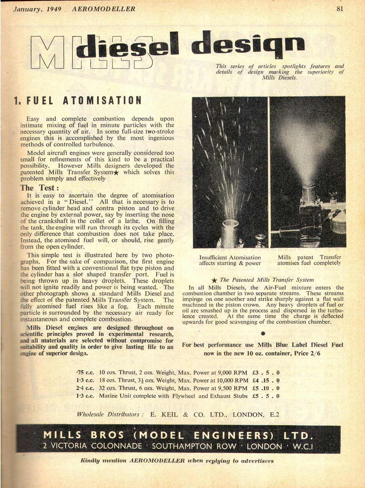
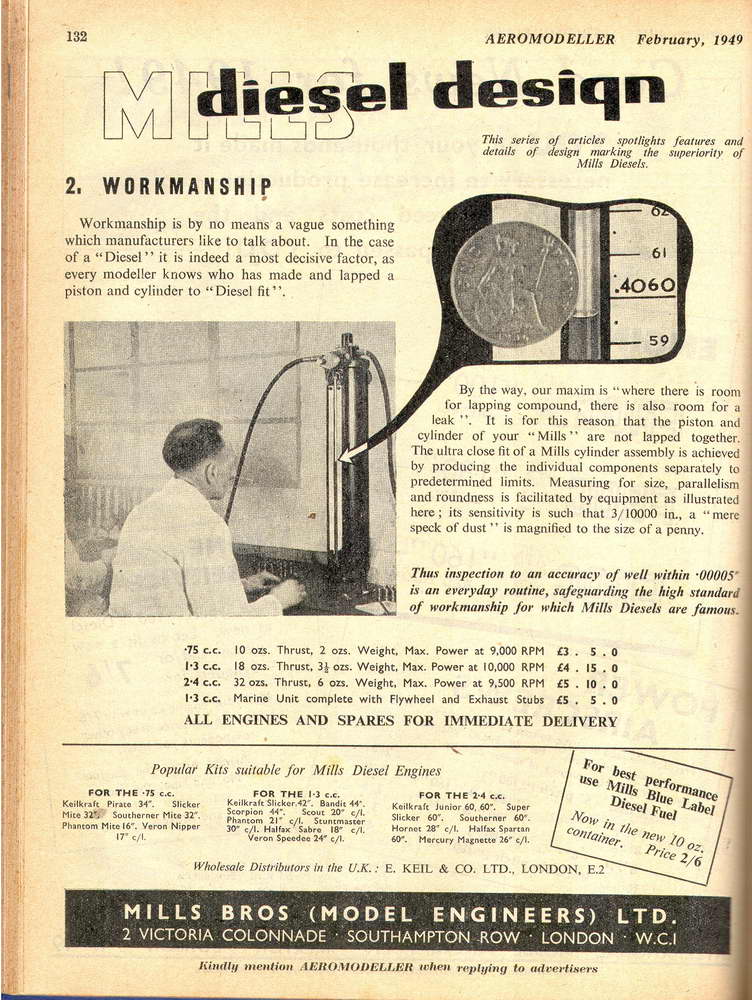
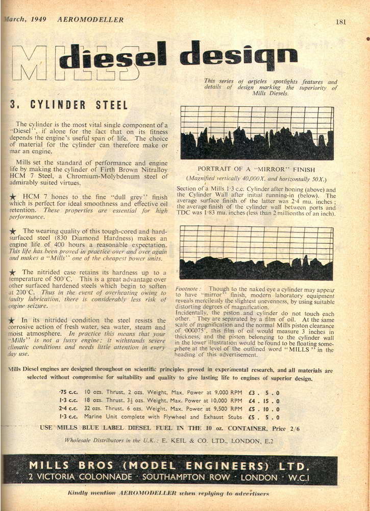
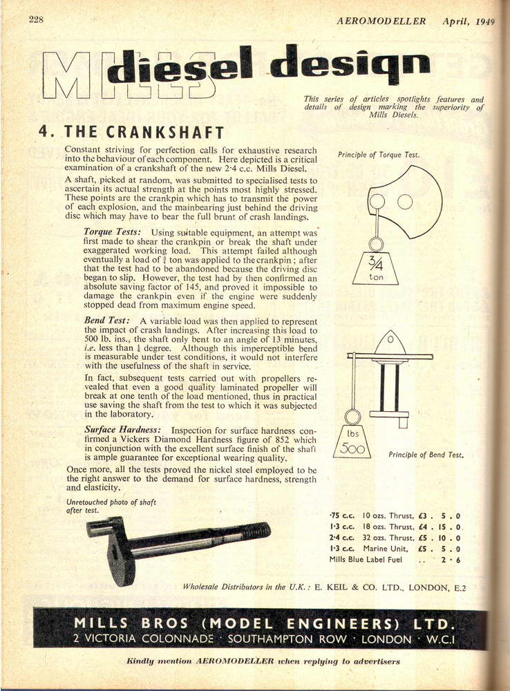
In 1494, to promote the Mk II 1.3, Mills Bros published a series of what we'd today call "Infomercials" under the title "diesel design". There were four of these as seen above. The first in the series that shows how the patented Mills transfer system provided superior atomization pegs my scept-o-meter and bends the needle. I think that with careful adjustment of the needle, any engine could be posed to show both characteristics. That's one patent I'd like to read carefully. The other pages in the series are more kosher, though rather biased to show Mills in the best light—and why not as it was their dime, so to speak.
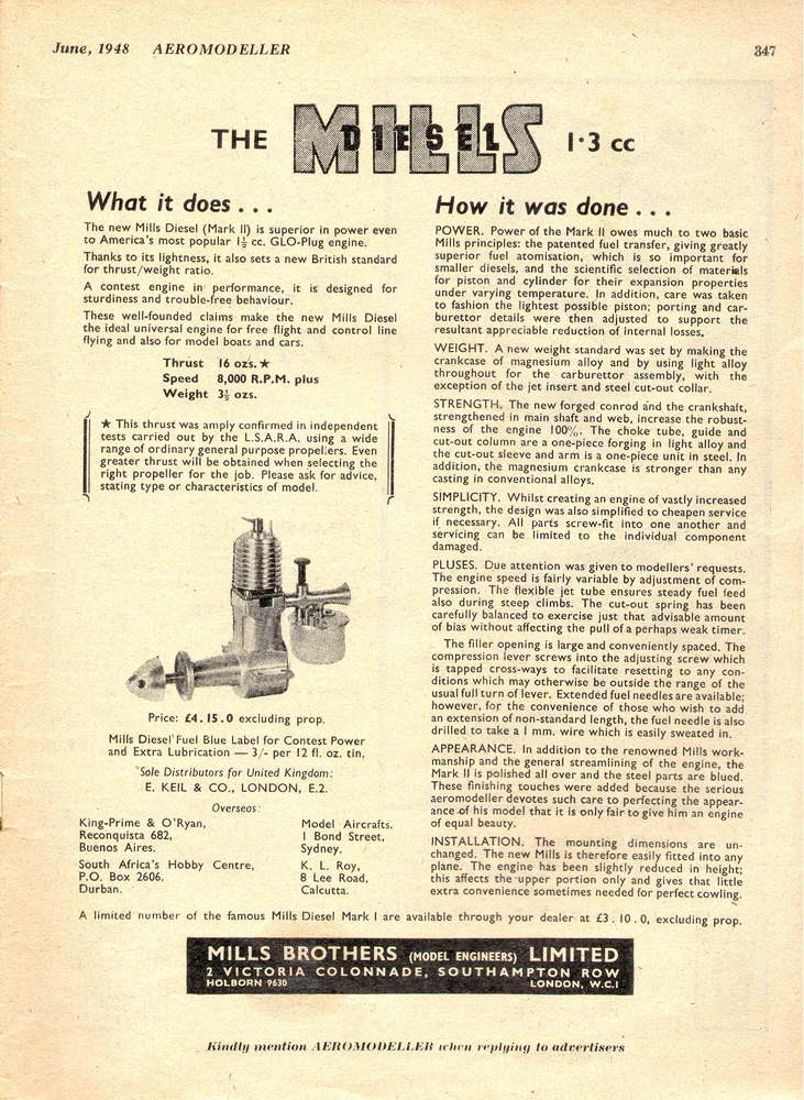
It's worth examining the first add for the Mk II engine that appeared in the Aeromodeller for June, 1948. The most common Mk II's around today have a black, chromate finish applied to the magnesium crankcase as a corrosion retardant. But note the photo and accompanying words that show that polished case versions must have at one time been available, however briefly. Where are they today? Gone and dusted most likely. As my friend Bert Striegler is fond of observing, magnesium is always trying to return to the sea from whence it came!
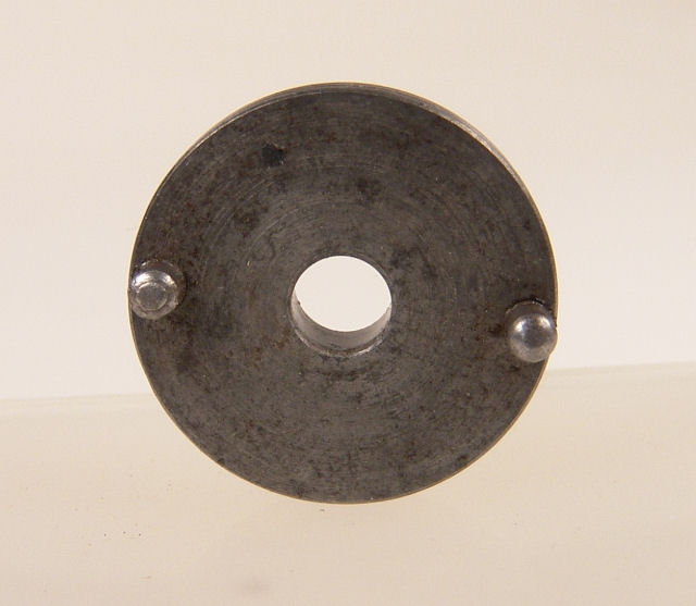
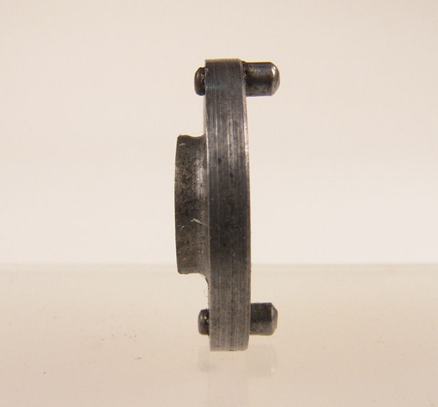
In common with other engines of the period, the Mk I prop driver was plain (ie, un-knurled) and fitted with two 3/32" pins as seen here. It fitted to the delicate shaft on a light taper. The shaft itself ran in a bronze bush. Early engines had a one piece bush. This later changed to a two piece arrangement that provided thrust faces for tractor or pusher operation. As is normal with this arrangement (frequently employed by ET Westbury since 1925), the gap between the bushes provided a lubrication reservoir. The Mk II retained this feature for a time before reverting to a single bush. Mills departed from common practice with their piston. Instead of the more usual cast iron, the Mills pistons were hardened and ground tool steel. As seen in "diesel design #2", pistons and liners were batch manufactured, measured, and appropriate fits selected. This process, I'm told, is ideally suited to high volume manufacture.
The contra piston was also steel, fitting well down in the cylinder at the running setting. To show just how far down, Bert Streigler made what he calls his "Bulldog Mills" from an Indian Aurora copy by throwing away all the excess and fitting an ED "Penny-slot" like combined cylinder had and compression screw. The roof of this item formed the actual combustion chamber, sealing via a hi temperature O ring bearing against an unthreaded section on the outside of the cylinder liner. Bert reports that his Bulldog, apart from being lighter and smaller, did not sag after heating up as diesels are wont to do. Bert concludes that the large heat sink above the piston keeps the top of the engine too cool, while the piston heats up resulting in it tightening up as it reaches operating temperature—hence the sag in RPM from cold start. Incidentally, the deck height of the case and between centers distance of the conrod was reduced by 4mm with the Mk II introduction—another change contributing to the weight loss.
Nailing down dates for the various marks and revisions is more difficult. Ref [9] states that the Mills 1.3 entered the market in 1946. That would be the Mark I, Series I. The reference goes on to state, "The engine was superseded in 1948 by a Mk II version, of somewhat lighter construction, and, late in 1949, a modification to the intake porting was responsible for a substantial improvement in performance." The table accompanying the text quotes the BHP at RPM as being 0.08 at 8000 (1948), and 0.10+ at 10500 (1950)(sic). The changeover from Mk I Series I to Series II cannot be dated. Worse, repaired engines sport heads and venturis different from those with which they were originally fitted. And as pointed out in the published serial number reviews [4], the numbering scheme was disjoint and probably has little bearing on the numbers actually built.
The Mill engines quickly acquired a justified reputation for ease of handling, reliability, and power. Even today, they are prized for their ability to start easily and swing a large prop in free flight competition scale (frequently while tightly cowled and largely inaccessible), and for their instant re-starts in free flight "scramble". This is a peculiarly Australian event with the prize going to the model having the highest aggregate flight time over a set time period and requiring a retrieve and return to the starting line before each short max duration flight. It is often conducted for an hour just before dusk, or even at night! Regardless of whether the design itself derived from a continental engine, the Mills 1.3 has now been sufficiently copied to have become an archetype in itself.
References:
| [1] | Noaks, M: The Mills Story Part 1, Model Engine World, Volume 2, Number 18, October 1992, p6. |
| [2] | Noaks, M: The Mills Brothers Story continued, Model Engine World, Volume 2, Number 19, May 1995, p7. |
| [3] | Schroder, RJ: Engine-uity: Mills Brothers Engines Part 3, Engine Collectors' Journal, Number 99, March 1992, p8. |
| [4] | Schroder, RJ: Engine-uity: Mills Brothers Engines Part 4, Engine Collectors' Journal, Number 100, May 1992, p5. |
| [5] | Elton, R: The Old Mills Magic has us in its spell, SAM 35 Yearbook #7, (undated, probably 1998), p78. |
| [6] | Sparey, LH: Engine Review #3: Mills 1.3 Mk II, Aeromodeller, Volume XIII, No 150, July 1949, Model & Allied Publications Ltd. |
| [7] | Laidlaw-Dickson, DJ: Model Diesels, Harborough Publications, London, 1947, pps 28, 30. |
| [8] | ibid. pps 65, 67. |
| [9] | anon: Engine Review [1951], Model Aircraft (The Journal of the Society of Model Aeronautical Engineers), Percival Marshall Publishing, Vol 10, No 5, May 1951, p251. |
| [10] | Fisher, OFW: Collector's Guide to Model Aero Engines, Argis Books, Watford, 1977, p32. |
![]()
