The K-Dee 15cc Special
aka: The Atwood Silver Crown 15cc Special
 |
| Name | Atwood Silver Crown Special | Designer | Bill Atwood |
| Bore | 1.000" (25.4mm) | Stroke | 1.125" (28.58mm) |
| Type | Spark Ignition | Capacity | 0.982 cuin (16.094cc) |
| Production run | Low, plus kit built | Country of Origin | USA/Australia |
| Photo by | various | Year of manufacture | 1938..1974, or later |
Background
The American Model Engine Encyclopedia (AMEE) and Anderson's Blue Book tell us this engine was produced by Champion Products Co in 1940, and was only available as a kit. Charley Bruce, writing in the Engine Collectors' Journal (ECJ) #143, notes that some engines in the "Crown" series were fully made to order by Bill Atwood himself. Others, made from kits will show variations reflecting the builder's choices. We've seen that "modern" kits also exist, so it will be somewhere between extremely hard and impossible to identify the actual provenance of any Silver Crown encountered today.
The "Crown series" were named Blue, Red, Green, Purple, and Silver. The "Silver Crown Champion" was a 15cc air-cooled boat engine; the Purple was a 10cc version of the same engine. The Blue Crown was a 10cc race car engine with a single shaft rotary valve at the opposite end to the flywheel. The Red Crown, another car engine, had an updraft shaft rotary valve on the same end as the flywheel. The Green Crown was an aircraft version of the Red Crown, fitted with a backplate mounted fuel tank. The colors were for catalog identification purposes only—no color was applied to any of the fully assembled Anderson engines.
The Kits

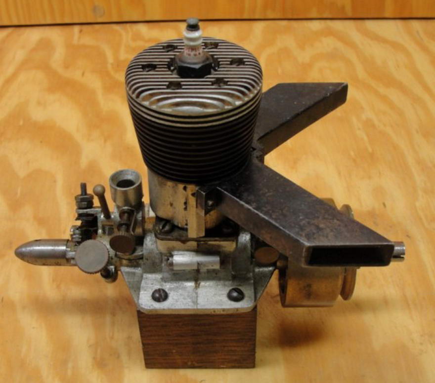
This kit-built Silver Crown appeared on the cover of ECJ #144. The engine builder has added a different style choke arrangement for the front intake. Adjusting those twin needles might be a chore and the idea itself is somewhat questionable. There is a limit on venturi throat area for a given crankcase volume and pumping efficiency. As throat area increases, a point is reached where the engine stops being able to draw fuel, unaided by pressure. Doubling the number of inlets will not allow us to go past this limit as it is limited by primary compression. You might then argue that having two opposed sources of fuel/air entering the crankcase may provide better mixing, somehow. Given the transfer arrangement on the Silver Crown, this seems a bit optimistic. Still, one could always "choke-off" the front inlet and then have only a single needle to fiddle with.

What remains in question now is how the original plan came to have that "export" note on threads added. ECJ says that several kits for the Silver Crown are known to exist. We know of an American one produced by Denny Hitson, and an Australian one made by "K-Dee" and sold through Hobbyco, of Sydney, as seen here in their 1958 catalog.

We are certain that the "good" casting set with the two different types of venturi castings is a Hitson kit, while the rougher ones with a single style of venturi casting was produced by K-Dee (who also produced rubber powered "stick and tissue" scale kits). To add to the confusion, Hobbyco was started in 1935 by Robert Lowe and named "K-Dee Pty Ltd" after his wife's initials. In 1947, he changed the name of the company to Hobbyco Pty Ltd. This implies that the castings were made sometime before 1947, appearing, while stocks lasted, in later Hobbyco catalogs under the original name. Just who cast the parts for K-Dee/Hobbyco is anyone's guess.

In both cases however, the plan seem to be a copy of the two original Anderson plates and the distinctive lettering style strongly suggests that either Thos Head added the BA/Whitworth note and changed the engine name and title block, or K-Dee enlisted an artful forger to make the change in a good copy of the plan lettering style. While Hobbyco was "K-Dee", and probably for a while thereafter, all was well. But at some point, some person unknown decided that while the name of the engine was ok, a title block saying "K-Dee Pty Ltd, Sydney, Australia" was confusing, embarassing, or something, so this part of the stock of plans was snipped.

Showing just how far an individual kit builder's variations might range, this pair of engines were machined from the "K-Dee" castings by an Australian builder. While both have been "aero-ized", the front (black crackle finish) engine retains the dual venturi arrangement but has the timer moved to the rear. The rear (green crackle) engine is front induction only, with an enclosed timer located back at the front! Notice how the black engine theme is continued by the use of black cap head screws. While castings may be a bit rough, the builder shows what some talent can achieve. Perhaps the eBay engine seen earlier was based on a K-Dee kit too as we can see the unused choke boss on the rear (flywheel end) venturi.
")
What Denny Hitson (USA) did is confusing. His castings are nice. One set found its way to the UK and came with the full, unaltered Anderson plan. Another, also in the USA, had the plan with the thread note, and all of the title block cut away. So we can't quite close the book on this one yet—more information always welcome.
Why Dual Intakes?
The question of why Atwood chose to use dual intakes is open to conjecture, so let's look at a possible reason. The crankshaft diameter shown on the plan is 0.436" with a gas passage diameter of 0.282" (9/32" assumed, the plan is unclear on this). That means the crackshaft walls are 0.077" thick at the highly stressed end near the crankweb. That's not a very large bore to feed a 15cc petrol engine. Remember, the ideal stoiciometric ratio, air to fuel, for petrol is between 12.4:1 and 14.7:1. That's a lot of air compared to methanol based fuels where the ratio falls to between 4.0:1 and 6.45:1 (with no nitromethane content). Assuming the crankcase geometry provides for adequate pumping capacity, by using two inlet valves, Atwood doubled the gas passage area and hence increased the engine's ability to draw in air, thus providing a heavier optimized fuel/air mix to feed the large 15cc displacement.
Could the same effect be achieved with a larger diameter crankshaft, allowing a larger gas passage? Yes. The total gas passage area is 0.124 square inches. If we maintain the same 0.077" wall thickness, the shaft would need to be 0.553" in diameter. That's rather enormous, but still might have been a better choice, since—all things being equal—friction in a plain bearing is proportional to half the journal diameter (only one ball race is used at the inner ends of the shafts). Hence, the bearing friction of the large shaft will be less than that for two smaller ones.
There is a downside though. As well as requiring a larger ball race, to achieve the same inlet duration in the large diameter shaft with the same venturi opening, we'd need to increase the port opening to occupy 91° of the shaft, as compared to 75° for the smaller shafts. This weakens the shaft, meaning thicker walls might be needed, meaning more diameter, meaning an even greater port width... but then, all engine design is a series of compromises, after all.

Apart from the Crown series, few other engine designers have gone down the twin rotary valve route. Bill Atwood must have seen some value in this idea as his Champion engines continued to combine front rotary valve with rear drum or rotary valve induction from the 1940 0.597 cuin spark ignition Champion Race Car engine, to the glow plug ignition .625 cuin, Glo-Devil "GD" of 1948. Interestingly, all of these had a single needle valve and "smoke-stack" venturi at the rear with a plenum chamber under the engine feeding fuel/air mix to both inlet valves. Research indicates that only one other company tried this combination, that being JL Engineering who produced replacement front and rear assemblies for the 1940 Denny-Mite piston ported engine. The owner plugged the side valve inlet, then fitted either the front rotary valve accessory, or the rear drum valve component, or both! Strangely, it did not seem to catch on.
![]()
