Hybrid Hornet
| Name | Hornet | Designer | Johnson |
| Type | Spark Ignition | Capacity | 0.643 cuin |
| Production run | 1 | Country of Origin | USA |
| Photo by | Bert Streigler | Year of manufacture | circa 1948/9 |
Background
This is not your everyday Hornet. The engine came into the hands of Texas Motor Boy, Bert Streigler who performed an excellent resatoration job on it, getting a few surprises along the way. I'll let Bert tell the story:
Now, here is the story of this unusual and unique engine. I got it several years ago and aside from being totally filthy and having a large section broken out of the exhaust stack, it is otherwise the same. The guy who had it died and it was in his estate, so I bought it. It has several unusual features, but the listing with it said it had all Hornet parts internally, but I never took it apart to check all this out. Today, I dismantled the thing and quickly determined that it had only one Hornet part - the connecting rod. Everything else was unique!
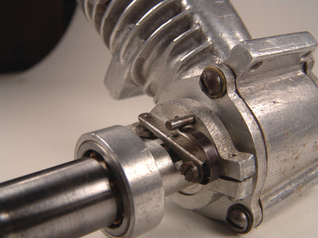
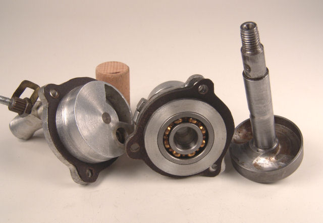 For instance, look carefully at the picture of the parts and notice that the crank web is very thick and carefully balanced on the front of the web by milling out some slots, and then later putting in some solder to fine tune the balance. I am not real sure of the reason for all this on the shaft, but it is different. The shaft is carrier on two ball bearings, and so is the rear rotor! The rear rotor is also carefully balanced on it's back side, with due care to not messing up the inlet timing. The piston is a fine sand casting that has been carefully lightened to the maximum extent. It has a very high dome, but no side fence corners like the original Hornet used. Two conventional rings are fitted.
Another difference is that the bore and stroke are very different from the Hornet. The Hornet I have measures .940 bore, .875 stroke for a displacement of .607 cubic inches, while this thing measures 1.00 bore, .807 stroke for a displacement of .643 cubic inches. The sleeve has square ports with the usual ribs, but the ribs are extremely thin to maximize gas flows.
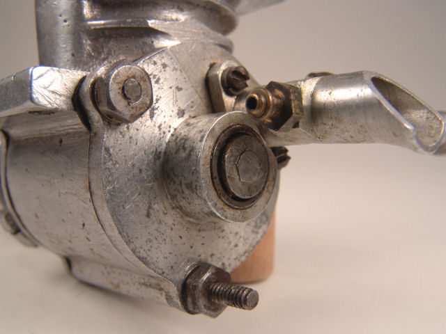
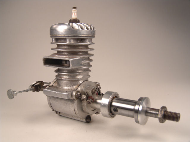
This engine was probably built by a pretty famous race car buff in Houston right after WW2. His name was Johnson and he is best remembered in race car circles for his unusual split-body timers that could be more easily installed in a race car. A careful inspection of the pics I sent will reveal that the lower half of the timer is held in place with two screws. He sold these to all the race car guys and made special bodies for every type of engine then commonly used in race cars. This interest in cars likely explains the long extension on the crankshaft and it was likely used for directly driving one car wheel. It could have also been used for a prop if desired but it would result in a really long nose! The extension threads over the end of the shaft with tight threads, and is held in position by a set screw.
 Another tip-off that it was a car engine is that there is no provision for adjusting the timing while the engine is running, and three timing positions are marked on the front plate. My guess is that the Dooling 61 cam upon the scene, and the attempt to develop this unusual engine simply never came to fruition. The one I have is likely the only one around and was probably a prototype. The only thing I know for sure is that it was made by Mr. Johnson, probably around 1948 or 1949. Workmanship in the engine is excellent. Tim, you might know some race car guys who know more about the engine and it's maker.
Restoration
After looking at the photos, I asked Bert if the crankshaft had been fabricated (as I could see no way to machine the unusual balance as neatly), and what he head done to fix the broken exhaust. Here's Bert's response:
There was a large piece simply broken out of the bottom of the exhaust up toward the front of the engine. I used CA to cement a piece of smooth plastic inside the exhaust, and then applied JB Weld, which is some kind of epoxy like araldite mixed with aluminum powder on the outside where I could get to it and shape it back flat. After the shaping was done, I removed the plastic "dam" inside the exhaust with some acetone. Then I sanded the repair smooth and mixed up some aluminum powder pigment with a little clear epoxy and simply rubbed it on. It blended in perfectly and is really hard to see even when you know where it is. The piece that was missing was about 1/2" long and really left the engine looking ugly. I guess if I ran it I would have it all to do over again!
The Original Hornet
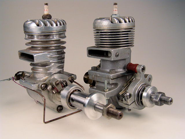
Just for comparison purposes, I asked Bert to snap a shot of a 'genuine' Hornet for identification and comparison and purposes. It's like the old English comedy sketch of two northerners comparing their birds the goes something like ...had one jous' like that; beak at one end, tail t'other; bird between... Which is to say, not a lot. The photo shows the 'real' Hornet on the right with Bert's hybrid on the left. We both agree that seen side by side, the hybrid has a certain charm to it that the other lacks.
![]()