ED 1.46 "Hornet"
 |
 |
 |
| Name | ED "Hornet" | Designer | Basil Miles |
| Type | Compression Ignition | Capacity | 1.46cc |
| Bore | 0.531" | Stroke | 0.400" |
| Production run | Large-ish | Country of Origin | England |
| Photo by | Ron C | Year of manufacture | 1952-1963 |
Background
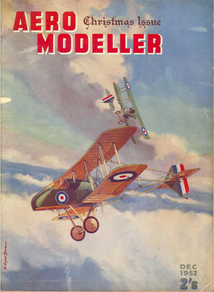
The first advertisement for the ED Hornet appeared in the 1952 Christmas issue of the Aero Modeller. A brief entry in the Trade Notes of that issue said that supplies would appear on dealers' shelves "soon". This pre-announcement is understandable as up until the mid 1960's, the Christmas issue of Aero Modeller was termed a "bumper" issue, being almost twice normal size. The '52 issue also included two free, full-size plans, Bill Dean's Madcap, and Vic Smeed's Debutant. These special, annual issues were eagerly awaited by British Commonwealth modellers, so the full page ad, coupled with the low price doubtless created good early demand for the engine.
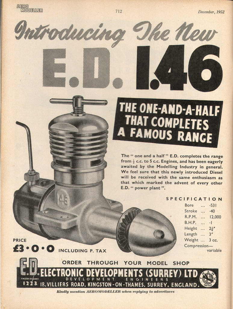 At this time, the engine had not yet been christened and was simply called the "E.D. 1.46". The engine filled a gap in the range for competition classes that called for engines under 1.5cc (hence the slight margin on displacement). The range comprised the 0.46cc "Baby", the 1cc "Bee", the 2cc "Competition Special", the 2.46cc "Racer", the 3.46cc "Hunter", and the 5cc "Miles Special" (seems like someone at ED really liked "point four-six" for some reason).
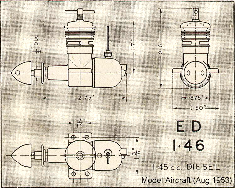
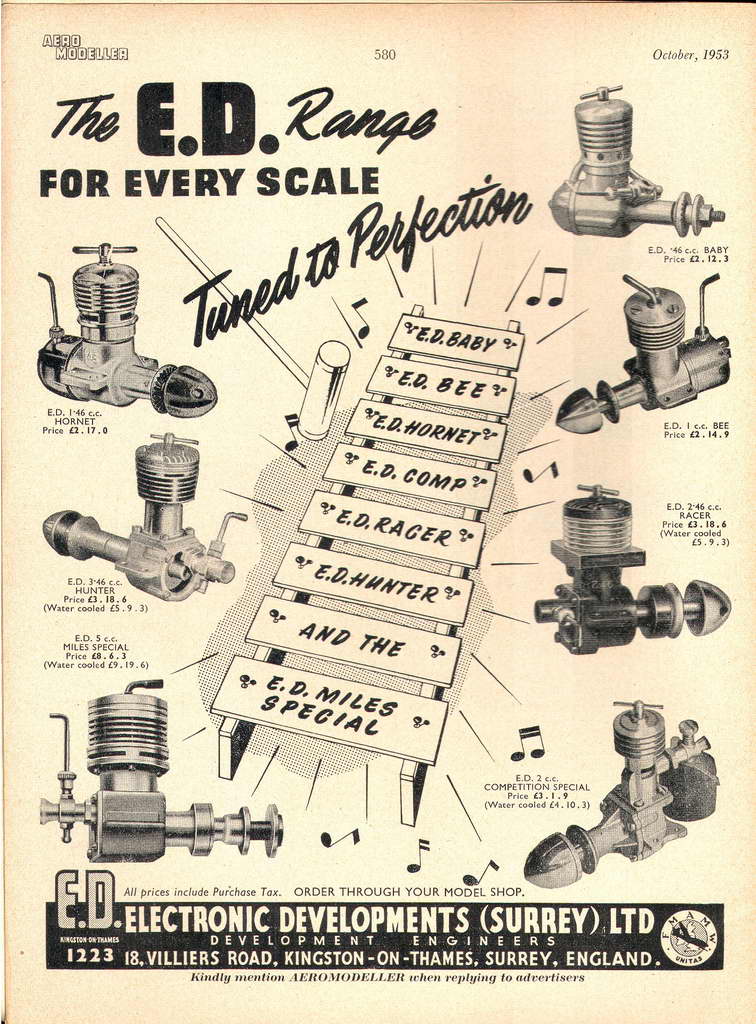 The follow-up campaign was sporadic. No further full-page ads appeared and often, ED chose to feature their R/C gear, engines not being mentioned at all (for a fully detailed history of ED, see the The ED Story). Ron Warring reviewed the engine for the February 1953 issue of Aero Modeller [1]. Rival publication, Model Aircraft carried an anonymous review in their August issue (it is generally believed these anonymous reviews were conducted by Peter Chinn). Whoever he was, the reviewer said that the engine was newly named the "Hornet" [2], a fact born out by the ED ad appearing in the Aero Modeller the following month.
Description
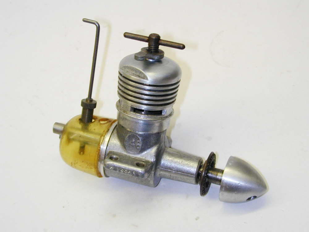
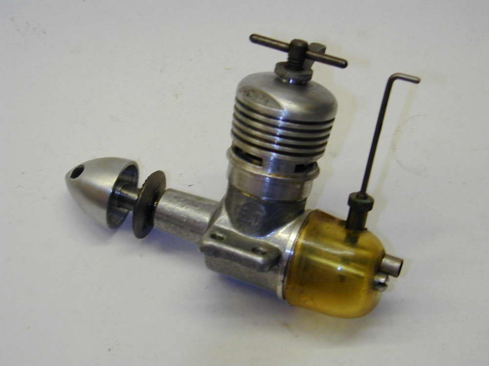
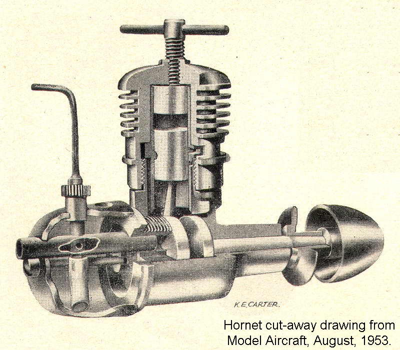 The "Hornet" was a peripherally ported compression ignition engine with rear rotary valve induction, fitted with an integral plastic fuel tank suitable for free-flight use. The 7/32" diameter crankshaft ran un-bushed in the cast aluminium crankcase. Both liner and piston were hardened steel rather than the more normal steel/cast-iron combination (Dick Richards' review says the piston is cast-iron [3], but it is most certainly not on the three examples I examined). The liner dropped into an opening in the crankcase that was 0.020" larger than the liner diameter. It was centered and retained by the cylinder cooling jacket which screwed onto the projection of the crankcase. This resulted in a 0.010" wide peripheral cavity that formed the transfer passage to the three transfer ports located immediately under the cylinder flange. This scheme certainly reduced manufacturing tolerances and operations. It first appeared on the ED 0.46cc "Baby" that had been introduced in April 1952.
The engine appears quite conventional until you start measuring things. The bore is 17/32" (0.531"), while the stroke is only 0.400", the same stroke in fact as the 1cc ED Bee. Comparison strongly suggests that the shaft, drive washer and spinner nut were, in fact, ED Bee components, as is the backplate, rotary valve, intake, needle/spraybar, fuel tank, and the horse it rode in on! The result is a bore/stroke ratio of 1.327. Most other 1.5cc diesels of the period are nearer to "square". The result is a comparatively low piston velocity. This would be good for wear, but things get really interesting when we look at the timing.
 Line other manufacturers, ED used a thin slitting saw to produce the peripheral porting by making three 0.047" wide cuts on 120° radials. These were centered in the cylinder flange for the exhaust, and just touching the lower flange face directly below the exhaust ports for the transfer. This is fine, but means that the exhaust must fully open before we get within coo-ee of commencing transfer. If we make exhaust timing conventional, transfer will be of a rather short duration. Conversely, a conventional transfer figure will result in a very large exhaust period and hence, an "early" opening point.
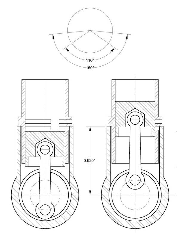 As this drawing, made from measurement taken from a Hornet in my collection shows, ED chose this latter route. The transfer is a respectable 110°, resulting in a gigantic 169° for the exhaust. This early exhaust opening means that we vent pressure well before it has finished doing the work it could have done. This also means that the exhaust exits at a high pressure and hence, velocity. The result should be an engine that is not as powerful as it could be, but with an exhaust note that certainly sounds like a high-powered screamer. The Aero Modeller test figures however don't support this conclusion. The Model Aircraft BHP test figures, although lower, still show an engine equal or better than its contemporary peripheral-ported diesels such as the Frog 150 and Allbon Javelin.
| Engine † | Induction | Bore (inches) | Stroke (inches) | B/S Ratio | Disp. (cc) | Peak BHP/RPM |
|---|---|---|---|---|---|---|
| Elfin 149 BB | RRV | 0.503 | 0.460 | 1.31 | 1.499 | .158/13600 |
| AM15 | FRV | 0.518 | 0.430 | 1.21 | 1.486 | .152/14000 |
| ED Hornet | RRV | 0.531 | 0.400 | 1.33 | 1.452 | .148/10500 |
| Allbon Javelin | FRV | 0.525 | 0.420 | 1.25 | 1.490 | .135/11000 |
| Frog 149 "Vibromatic" | Reed | 0.500 | 0.460 | 1.09 | 1.480 | .122/12750 |
| Frog 150 | FRV | 0.500 | 0.460 | 1.09 | 1.480 | .120/13000 |
| Allbon Sabre | FRV | 0.525 | 0.420 | 1.25 | 1.490 | .120/13000 |
| Taipan 1.5cc | FRV | 0.511 | 0.453 | 1.13 | 1.523 | .120/11250 |
(† Data extracted from reviews appearing in the Aero Modeller, 1951—64)
Sadly, the data are suspect. The test equipment and procedure used may have been different between the tests and the test conditions (pressure, temperature, and humidity) are not noted. Add to this the fact that most were based on testing a single example of the type. We can but hope that they are indicative enough to allow us to say that ED's choice of an early opening exhaust for the Hornet did not result in a complete dog.
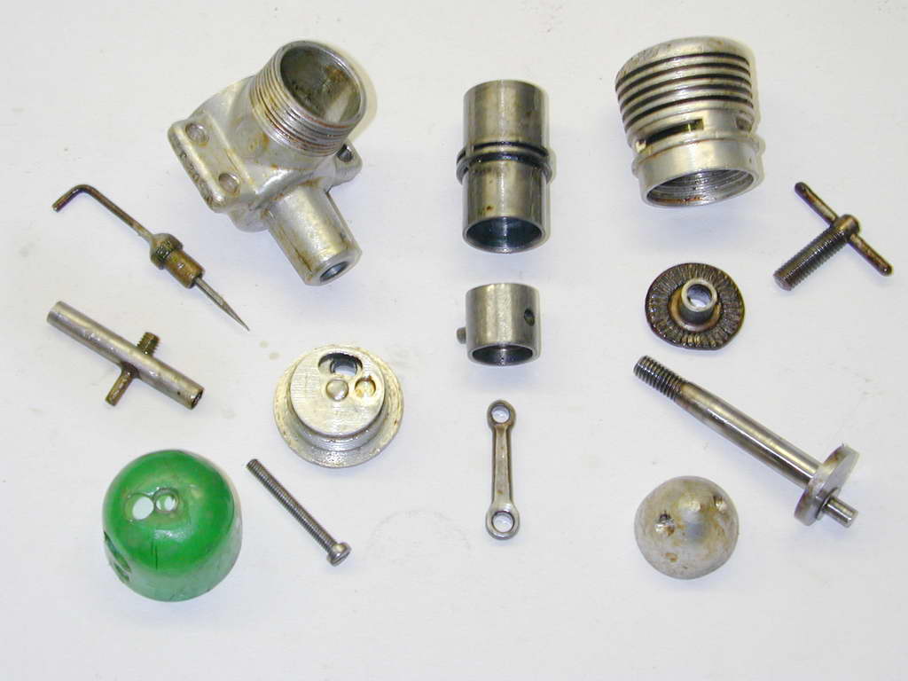
The rear rotary valve (RRV) would be conventional, except that like the ED Bee, the backplate screws into the crankcase. This means that the location of the inlet cannot be determined and machined until a backplate is screwed into a crankcase. The backplate can then be drilled for the venturi tube, but will only be in the correct orientation for that particular backplate/crankcase pair. The rotor is aluminium and marks on the edge indicate that it was stamped from 1/8" sheet. It is timed to open at about 45° after BDC and remain open for about 170°. It is permanently pinned to the backplate.
The cooling jacket is aluminium and a close sliding fit on the upper portion of the liner to keep it centered. Two milled flats provide the means for tightening it, although the spacing of the flats is just larger than a 6" shifting spanner of the period will accommodate, so expect graunch marks on well used examples. The conrod is hardened steel, making all the working bearings except the main journal hard steel on hard steel. The prop-driver, also steel, locks on a taper on the shaft. The shaft thread is 2BA and the turned aluminium spinner nut is extensively hollowed out.
Reassembly is a bit of a chore. Place the conrod, sans the piston, on the crankpin with the shaft, sans the propdriver, at TDC. The place the rotor so that the blind hole for the crankpin is inline with the venturi. Screw the backplate into the case until it is close to the crankpin with the venturi oriented at the "12 o'clock" position. Now push the shaft back and jiggle it to engage the rotor, squinting down the case opening as required to ensure it has been inserted into the blind hole and not the rotor inlet opening! The backplate can now be screwed up, pushing the shaft forward, and normal assembly resumed. In a word, painful.
There is a downside to the cylinder design. Cylinder/piston pairs wear into each other with a very specific piston/liner orientation. Reassembling the engine with the liner rotated a few degrees is highly likely to cause further wear. But due to the close fit of the liner in the cooling jacket, it is impossible to keep the liner still as the head is tightened, so assembling in the same position is impossible. The lesson is don't disassemble the engine any more than absolutely necessary.
Running
The impressive noise made by the Hornet has already been noted, despite the fact that this is not an especially high revving engine. Like many small RRV engines, it likes a squirt in the ports for starting rather than choking. The Aero Modeller tests found that it gave best performance on an 8x4 prop (wood) and would turn a 12" wood without strain. This makes it a good free-flight engine, especially for scale free flight models with large, round cowlings.The engine is quite easy starting which is good because the tank is a leak that does not have to wait to happen. The best we can say is that the ease of starting means you don't loose the lot before you can get it running and can top the tank up—upon which, fuel will start blowing out the filler hole as well as where the venturi passes through the rear wall! But for all that, it is a delight to handle; flexible in speed range, and insensitive to the needle setting. It does vibrate a bit (the crank not having any attempt at counter-balancing). ED must have noted this as later models came with a stamped arm type compression lock—a most necessary addition in my experience.
ED tanks deteriorate and crack with age. The tension the alloy retention screw places the tank under does not help either. Even if the tank leaks so badly as to be unusable, it's not a good idea to remove it as it provides support for the venturi which is a light press fit in the backplate casting. Without the tank, the venturi can also rotate, making it even more likely to vibrate loose.
Anyway, the batch number used the letters A to N, omitting the letter "I" to avoid confusion with "one". This roughly corresponds to the month of manufacture. So "A" is January, and "M" is December. The "A" is very scarce as a batch number, while "N" appears frequently. I assume they used N as an overflow if batches had been large enough over the previous year. The number after the batch/month number of the engine is simply the number of the engine in that batch/month. Finally, the last one or two digits is the year of manufacture.
Let's take "ZM 55/52" as an example: This is a Hornet (Z) produced in November/December 1952 and it was engine number 55 of that batch.
"RE 183/53" would be a Racer (R), made in May (E) of 1953 (/53) and is #183 of that batch.
To confuse the public, Bees were prefixed 1 (Ed: The "Bee" was officially the ED Mk 1. See the ED Bee review), the prefix "B" being used for the Baby. Mk 4's were prefixed 4, and Mk 111s prefixed 3, Mk 11s were not prefixed at all except with the batch number and Comp specials were numbered as Mk 11s but suffixed "/C". Occasionally you find the batch number before the type number.
After 1959, ED went on to a letter to indicate the year so as to avoid confusion. Hence A = 1960, B = 1961 and so on. After 1963 (the year of The Fire), I'm afraid it all went to pot, although after about 1966 a new system came in.
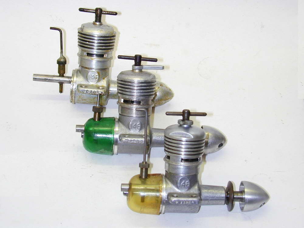
So now you know, and many thanks to Kieth for this valuable bit of historical data. Incidentally, Kieth has 12 Hornets in his collection varying from "New-In-Box" to "Junker Awaiting Rebuild". He confirms that they all have low values for the number in batch/month indicating low production figures for Hornets compared to Racers, Bees, Mk II's and Comp Specials.
Serial Numbers
ED was fond of stamping serial numbers on crankcases. Actually, they were more like a coding scheme than a sequence and appear rather "opaque" to the uninitiated—which included your author until a most enlightening email arrived from Kevin Richards of North Yorkshire. I'll let Keith explain:
Conclusions
 The 1.46cc ED Hornet was a powerful, noisy, easy to handle engine, well suited to sport and FF scale flying. It was a direct drop-in replacement for the 1cc ED Bee and I'm sure many an overweight and underpowered scale free-flight model took advantage of this. The engine continued in production until the 1963 fire put paid to all ED engine production.
From a construction perspective, the engine is simple and apart from the tedious business of the screw-in backplate positioned rotary valve, would have been easy to make. Certainly a modern engine builder looking for a fun project could do worse than replicate the liner/transfer system. The Richards article [3] suggests that Hornets were not made in as great numbers as other ED engines and are comparatively rare these days. If you have the chance to get one, be sure to give it a run. I'm sure that the noise will surprise and delight you—the neighbours may be perhaps somewhat less delighted...
The 1.46cc ED Hornet was a powerful, noisy, easy to handle engine, well suited to sport and FF scale flying. It was a direct drop-in replacement for the 1cc ED Bee and I'm sure many an overweight and underpowered scale free-flight model took advantage of this. The engine continued in production until the 1963 fire put paid to all ED engine production.
From a construction perspective, the engine is simple and apart from the tedious business of the screw-in backplate positioned rotary valve, would have been easy to make. Certainly a modern engine builder looking for a fun project could do worse than replicate the liner/transfer system. The Richards article [3] suggests that Hornets were not made in as great numbers as other ED engines and are comparatively rare these days. If you have the chance to get one, be sure to give it a run. I'm sure that the noise will surprise and delight you—the neighbours may be perhaps somewhat less delighted...
References:
| [1] | Warring, R: Engine Analysis No. 7: The E.D. 1.46, Aero Modeller, Model Aeronautical Press, UK, Volume XVII, Number 205, February 1953, p102. |
| [2] | anon: Engine Tests No. 50: The E.D. 1.46 c.c. "Hornet", Model Aviation, Percival Marshall & Company Ltd, Volume 17, Number 8, August 1953, p360. |
| [3] | Richards, R: Engines Old & New, Aero Modeller, Nexus Special Interests Ltd, Volume 83, Issue 748, April 1998, p20. |
![]()
