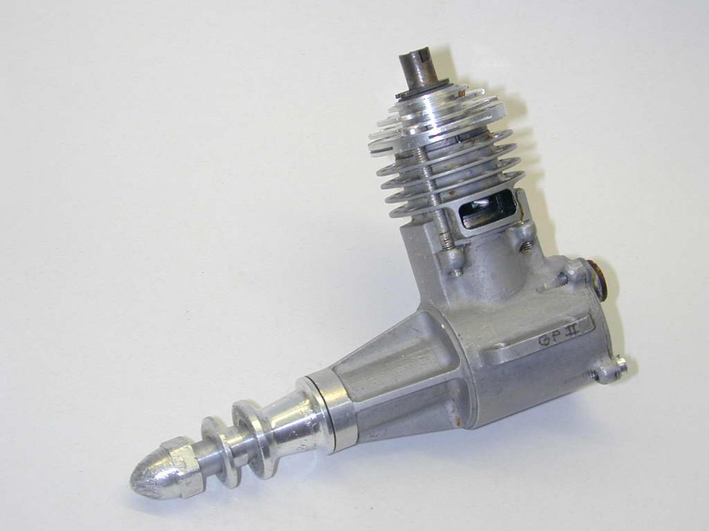
GP II
Created: 2006-11
Updated: 2006-12
 |
 |
| Name | GP II | Designer | Paul Bugl |
| Bore | 14.4 mm | Stroke | 15.2 mm |
| Type | Compression Ignition | Capacity | 2.48 cc |
| Production run | Low | Country of Origin | Denmark |
| Photo by | Jim Dunkin, Ron C |
Year of manufacture | 1979 |
Background
Knowledgeable collectors are going to look at the heading pictures and scream, "Bugl!" Then they'll look closer and say "...wait a minute...", and be right. The similarity to a PB 15D Mk 3 is very high, but there is no "BUGL" in raised lettering on the Schnurel boost bump, no external thread on the crankcase for the streamlined, screw-on nose cone, and some subtle differences in the fins—including the vertical holes between the bolt holes. The engine is a Geschwendtner-Petersen GP II, developed from the Mk 3 Bugl following Paul Bugl's untimely death from heart failure in 1978.
 The basic layout of the GP II is pure Bugl. Paul Bugl was born in Austria in 1930. He had a life-long passion for developing world-class diesel engines. Working essentially by himself, he produced a very small number of engines each year for FAI team-race, speed, and even free-flight power. His history and achievements have been well documented by American diesel enthusiast, Jim Dunkin [1]. Following Bugl's death in 1978, all parts and tooling were acquired by the brothers Hans and Jens Geschwendtner who moved production to Denmark.
Production of the Mk 3 continued from remaining stock until 1981 [3]. Reference [2] states that they produced a small number of engines in 1979 under the name "GB Model Engines". Note that the General Arrangement reproduced above carries the designation "BG", not "GB", so which is correct? Correspondence with Luis Petersen [8] confirms that the designation was BG and stands for "Br�drene Geschwendtner", or "Brothers Geschwendtner", not GB for "Geschwendtner-Bugl" as stated in [4]. A replica was marketed by Ukrainian manufacturer Profi in 2000 (not to be confused with the German company of the same name).
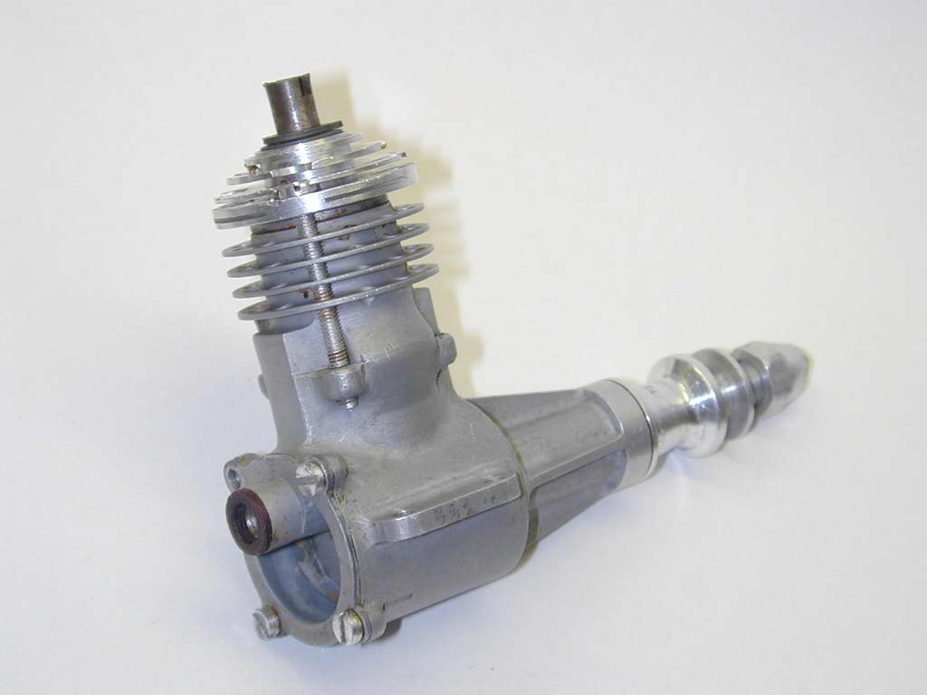
The engine at the head of this page is believed to have been made by another Dane, Luis Petersen. Luis was successful for Denmark in FAI team racing and remained an active judge and competitor until 2005. The engine came to me from Assistant Professor (retired) Niels Abligaard who had assisted Luis' continued development of the design by arranging to have a TiN coating placed on a crankshaft. TiN—Titanium Nitride—is frequently used today to place a hard coating on the more expensive milling cutters, drills, taps, etc. This however, was not a success [5]. The port engine lug has "GP II" electro-etched on it for Geschwendtner-Petersen, so, not counting the Profi replica, we have three rather similar engines: The eight PB 15D Mk 3 prototypes made in 1977, the PB 15D Mk 3 engines assembled by BG Models between 1979 and 1981, plus the GP II engine developed from the the Mk I crankcase by Petersen.
Construction
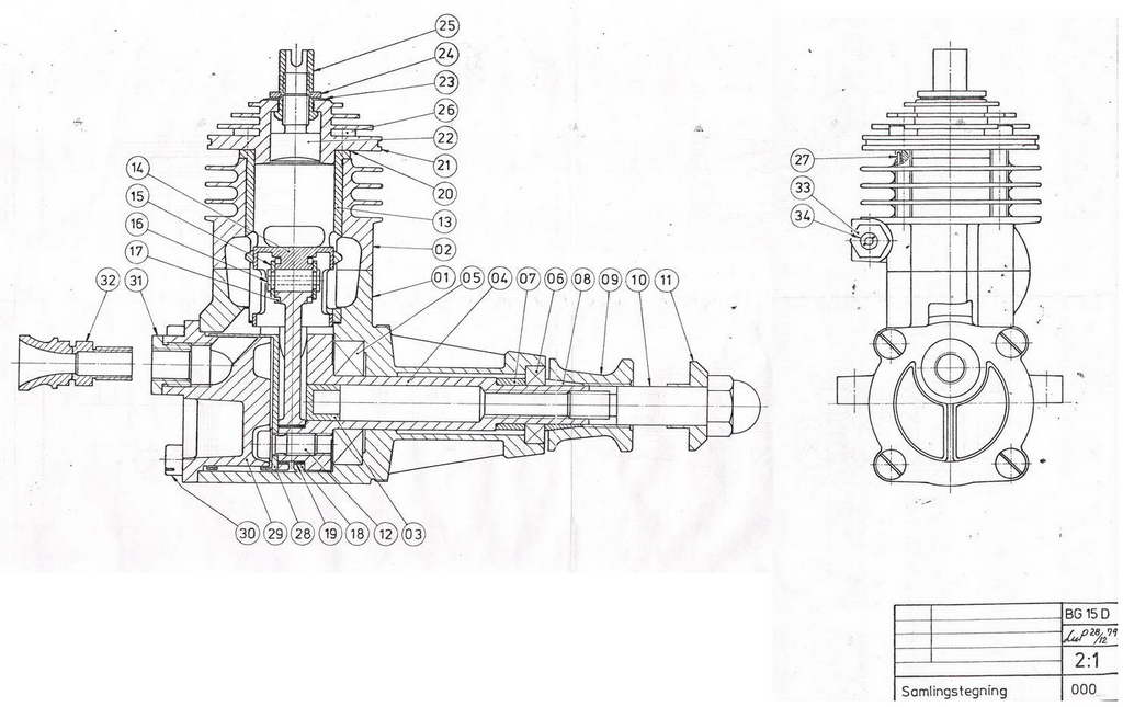
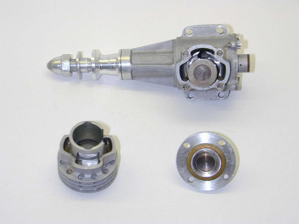
This is a light engine: 98 grams. In comparison, an Oliver Tiger Mk 3 comes in at 175 grams. The lightness brings with it a certain delecacy—risky when you consider that world-class tram-race events are invariably conducted over concrete! The engine is a twin ball-race, Schnurle-ported, compression-ignition engine utilizing a rear-mounted "bell-valve". Other unusual features are the hollow crankshaft, push-pull contra-piston and wrist-pin arrangement. Let's take these one at a time. It will be handy to have the GA picture above open and expanded to full screen as you read this section. The numbers appearing in brackets correspond to the circled numbers on the GA.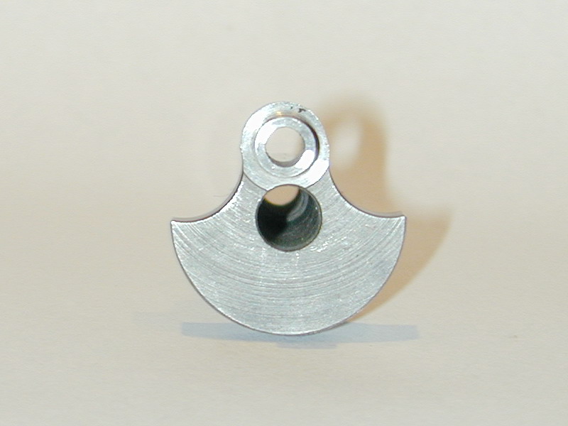 Easy ones first. The shaft (04) uses a screw-in stud providing a higher crash-resistance than a one-piece shaft. As seen here, it is drilled right through to reduce weight and plugged (03) at the web face to seal the crankcase cavity. Friction is minimised by having only a short, reamed section of the case nose that touches the shaft. For the most part, the bearing is relieved and does not touch the shaft. Notice the spacer (07) that spaces the bearings to prevent "loading" when the prop driver (09) pushes the split-cone (08) onto the inner shell of the front race (06). The long shaft and extension provided by the spool (09) serves two purposes. It helps stream-line the nose of the model, and sets the shaft resonance as determined experimentally by Bugl. The forward end of the aluminium spool is threaded for a short distance. This allows yet another special Bugl tool for to be fitted in order to remove the prop driver.
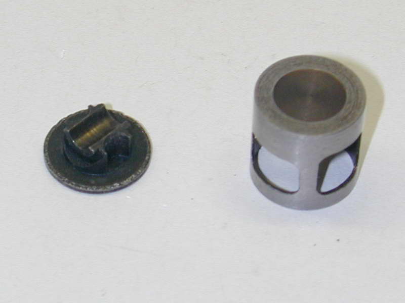
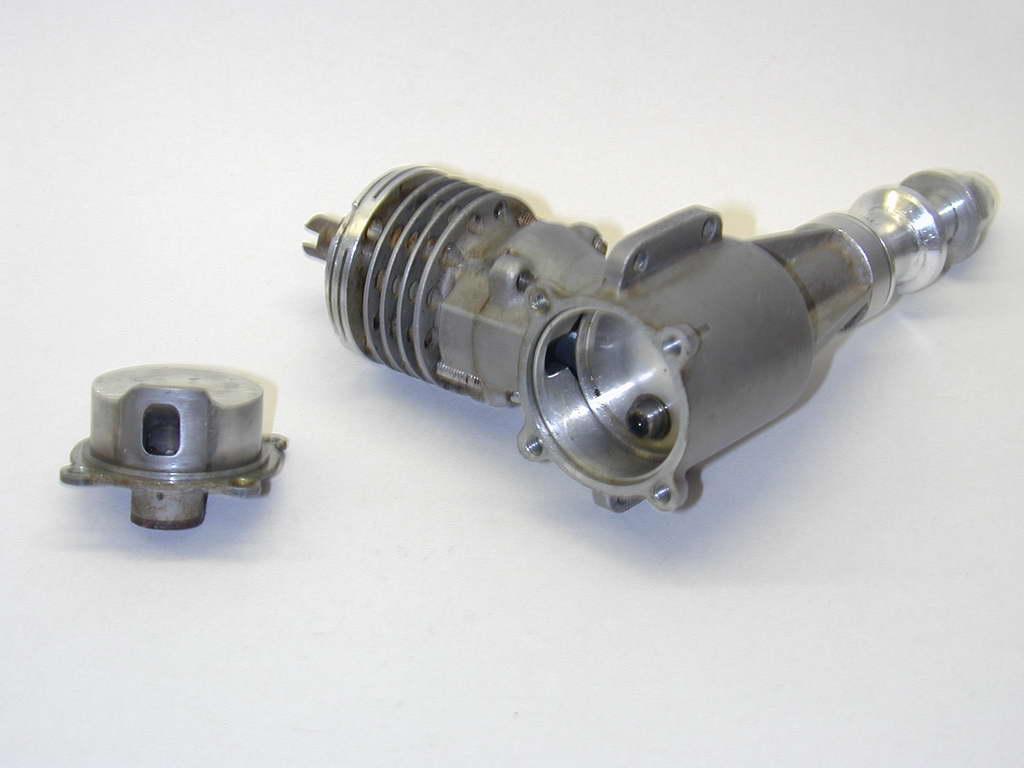 The inlet system is unique. As detailed by Jim Dunkin [1], Bugl developed a highly effective drum valve system while working for Austrian munitions company, Hirtenburger-Patronen (HP) during their dalliance with model engines arising out of an army RPV (Remotely Piloted Vehicle) program. Although designed by Bugl, the patent on the valve was held by HP, so following their rather acrimonious split, Bugl needed something sufficiently different that no claims of infringement could be levelled. His solution is the "bell-valve". It can be seen in the photo here—if you squint. It is a very thin, light weight, aluminium cup (28) with part of the wall removed by very sharp tooling (not EDM as previously suspected). It is rigidly affixed to the crankshaft by the screw (12) in such a way that it is very slightly eccentric with shaft and case cavity, riding a mere 0.002" away from the case wall. Notice that the bell end terminates some distance inside the case.
 Assembly requires a a special jig. The jig is a close fit inside the bell and has a lip that then locates in the case cavity opening very precisely. A hole in the jig allows the screw to be inserted into the crankpin and tightened up, thus locating the drum to be concentric with case cavity and backplate. Reference [6] states that the bell valve is positioned eccentrically by 0.005mm (two tenths of a thou: 0.0002") to accomodate deflection of the crankpin at TDC. I was unable to confirm this by measurement, but I'm not surprised—on either account!
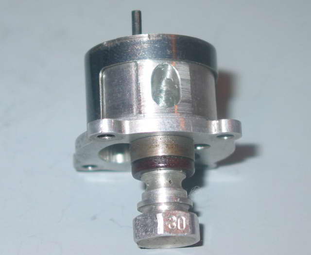
Now notice the inner shape of the backplate (29). Like the jig, it has a locating ring just in front of the attachment flange. The central part only contacts the bell-valve at points forming two tiny bands at the inner and outer ends, plus narrow longitudinal areas either side of the opening. In this way, physical contact is virtually eliminated.
The inlet path from the venturi deflects upwards towards the center of the piston at BDC. More on that later. The other aspect worthy of note is the insulating insert (31). This thermally isolates the venturi (32) from the engine to minimise inlet temperature which may boil off the highly volatile ether in the "diesel" fuel. This feature, or something similar, is now commonplace in FAI team-race diesels.
 |
 |
 |
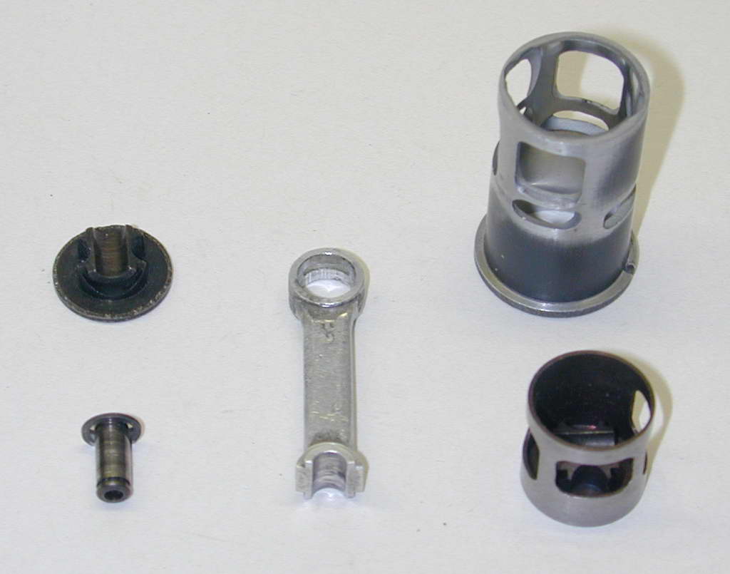
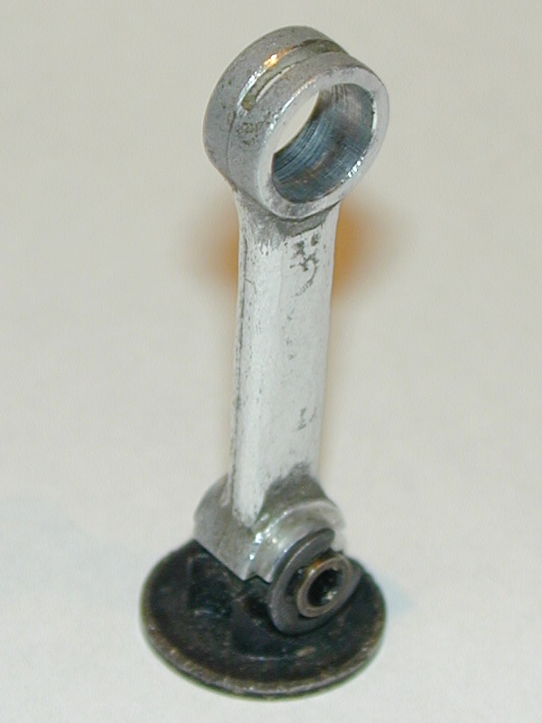
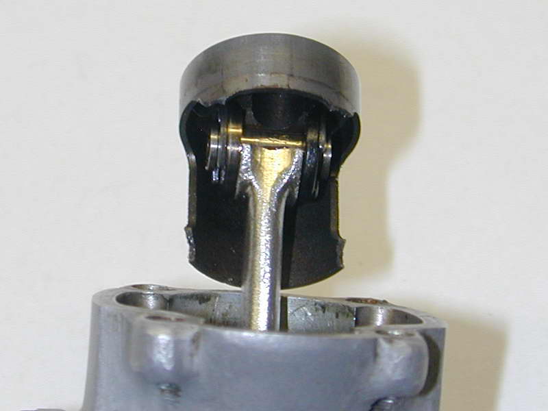
Ok, now it gets really unusual. The piston in the shot above, left may be broken, but the rod is not! Bugl reasoned that all the work loads of the rod little-end were carried on the lower face. Hence, we can do away with the top and save weight by reducing the piston height. The cost is some very intricate machining of rod and internal piston crown. As seen in the middle photo, a wrist pin (16) is grooved for circlips and placed on the cradle in the top of the piston. The rod (18) is stacked on top of that. The two are held together by thin washers (17) that ride in rebates in the ends of the piston cradle and outer rod faces. These rings are retained by the circlips (15). Now quite apart from Bugl's theories on friction, this totally relieves the piston skirt from any responsibility with regard to locating or retaining the wrist pin. As seen in the photo on the right, the piston walls are thin: 0.5mm (0.019") and the transfer windows for the main transfer ports occupy the place where we'd normally have to have thick walls for the wrist pin. This highlights another subtle advantage. Pressure from combustion is transfered directly from the head of the piston to the conrod via the wristpin. Normally, this force must be exerted on the wristpin by the piston skirt. So in addition to having to be proportioned to absorb and transmit the force, the piston walls are subject to distortion [6].
 Here is another broken piston that shows the assembled parts. The piston is steel with a 0.08mm circular depression in the center of the crown, used during machining for alignment as we will see in a moment. The big end is relatively conventional. It is slit for lubrication and carries a bronze bush (19). The machining of the piston has to be physically seen to be appreciated. This class of work is usually restricted to one-off projects. It is just not economical for a quantity productoin engine malking Bugl's achievments and dedication to quality all that more impressive.
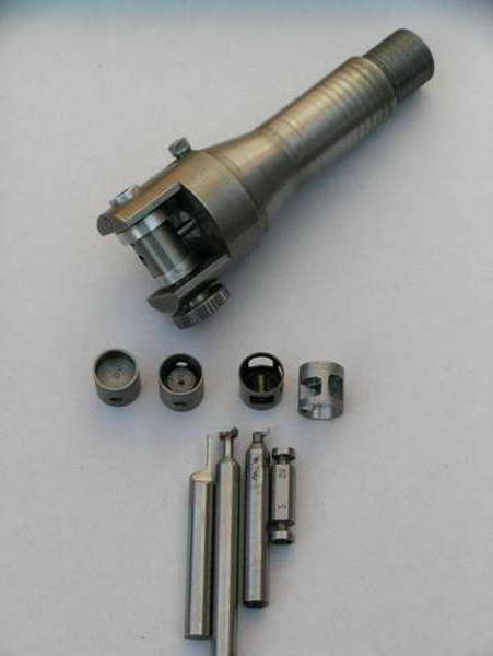 This shot was sent by Luis Petersen who worked with Bugl on the Mk II engine and subsequently did all "official" Bugl repairs until the project was acquired by his friends, the Geschwendtner brothers. The stages in piston machining and the cutters run left to right. The piston starts relatively conventionally, turned to pre-lapping size and reamed for the wrist pin. A groove was then rebated to produce the thin walls and the port opening cut. The proto-piston was then clamped into the jig which aligns the wrist pin with the lathe axis for machining the ends of the wrist pin pad with the single point tools that could be joggled in through the opening. The final operation was to machine away the central post with two angled cuts, and make some further weight reduction cuts. Remember the walls are only 0.5mm thick. Very sharp tooling, a steady hand, and experience are required to machine things like this.
 |
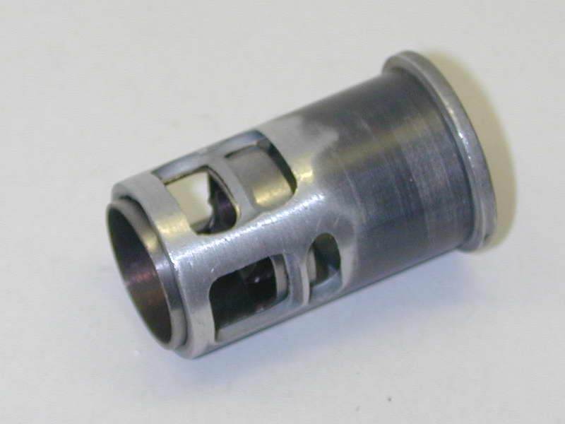 |
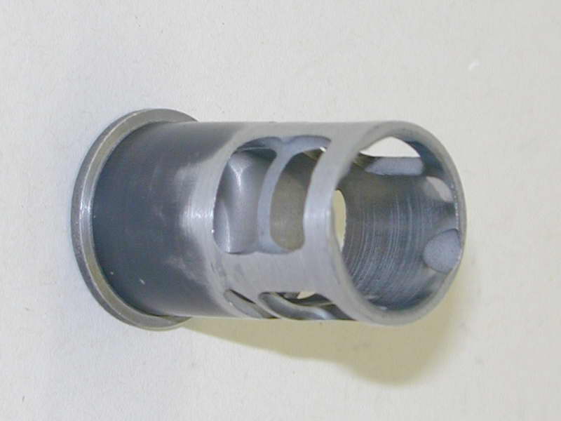
The cylinder liner (13) is aluminium, flash chromed in the bore. It weights nothing; something between 2 and 4 grams (my electronic scales only have 2 gm resolution). The liner is generously Schnurle ported; very generously! Remember that the bell-valve delivers the charge into the center of the piston. This cools the piston and lubricates the wrist pin. As the piston approaches BDC, the ports in the sides of the piston intersect with the lower transfer ports in the liner. A short time later, the crown opens the fore and aft transfers. These are machined at an angle to direct the flow upwards and away from the exhaust. A short time later the boost port opens. The upper boost port is sharply angled upwards. Luis Petersen informed me that the ports were not cut by Electric Discharge Machining (EDM), just very sharp tools and a steady hand!
 The aluminium head (21) actually provides part of the combustion chamber ceiling. It is fitted with a relatively small contra-piston (22) made from high-silicon aluminium. It has a threaded protrusion which screws into the adjuster (25) that is fixed in the head by the circlip (24). This makes the action push-pull via the thread. Again, common practice on high performance team-race diesels. The photo clearly shows the two-piece crankcase, split through the Schnurle transfer bulges. This allows the inside of the ports to be accurately formed and has been used by Taipan and others. Note the pin (27) used to locate the liner in the upper part of the cylinder. The parts (33) and (34), not present on the GP II example, are for a priming tube that connects to the filler overflow. This allows the pitman to fill and prime in one action via a special needle valve assembly.
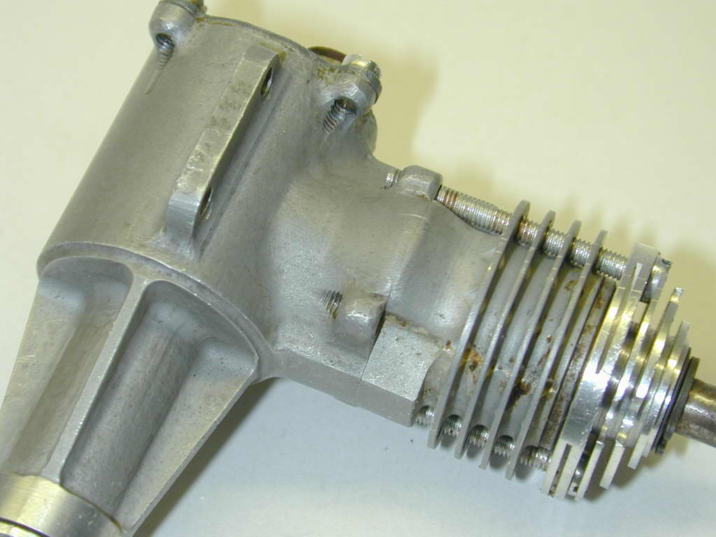 The registration between the upper and lower case sections, as seen here, is very, very good. The surface is a matt grey. Reference [2] states that the case may have been prodiced by EDM. This is not the case. Builder Luis Petersen has confirmed that the case was made from a Mk I Bugl case and glass-blown. The last item of note are the head bolts (26), and backplate screws (3). These are alloy, not steel. The aim was not weight reduction but to achieve the same thermal expansion and so avoid undue stress (aluminium expands more than steel with heat, effectively "tightening" the screws) [8].
Conclusion
The translated engine test of the Bugl 15D Mk 2 that appeared in Model Engine World reported a peak of 0.591 BHP at 19,000 rpm. The maximum rpm recorded was 26,000 using a Koster 7x2 F1C prop. In comparison, a pressure fed Rossi .15 glow did only 500 rpm better on the same prop [7]. Being a diesel, the fuel consumption of the Bugl would have considerably lower than that of the Rossi for essentially the same output, thus giving the Bugl the edge in team racing by giving greater "range". We can expect that the Bugl Mk 3 and the further developments made by Geschwendtners and Petersen improved on these figures.Just as the Oliver Tiger reset the bar for competition team-race diesels in the 50's and 60's, so did the Bugl in the 70's and 80's. It represents close to the limit of performance achievable without using exotics like ceramics. After reaching this level of refinement, success comes down to preparation, consistency, and reliability of engine, model, equipment, pilot and pit-person (says he who is forever a bridesmaid in mouse racing  ). I'm greatly indebted to Niels Abildgaard for providing this engine for examination. Thanks, Niels.
References:
| [1] | Dunkin, J: The Paul Bugl Story -- Part 1, Engine Collectors' Journal, Model Museum, Colorado, USA, Volume 17, Number 6, July 1991, p1. |
| [2] | Dunkin, J: The Paul Bugl Story -- Part 2, Engine Collectors' Journal, Model Museum, Colorado, USA, Volume 18, Number 3, March 1992, p1. |
| [3] | Goodall, J: Cover Story ~ 2.5cc Bugl Team Race Diesel, Model Engine World, volume 7, issue 67, May/June 2000, p5. |
| [4] | Dunkin, J; Sitje, M: Bugl Addendum, Model Engine World, volume 7, issue 68, Aug/June 2000, p7. |
| [5] | Abildgaard, N: private email to the author, November 2006. |
| [6] | Petersen, L; (translator: Sitje, M): Bugl Test Report, Model Engine World, volume 7, issue 69, Nov 2000/Jan 2001, p6. |
| [7] | ibid. p7. |
| [8] | Petersen, L: private email to the author, December 2006. |
![]()