ML Dragonfly Twin
| Name | Dragonfly | Designer | Mark Lubbock |
| Type | Compression Ignition | Capacity | 1.6cc |
| Production run | 1 | Country of Origin | UK |
| Photo by | Mark Lubbock | Year of manufacture | 2005 |
Background
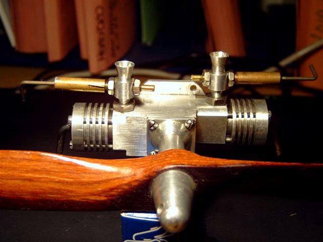
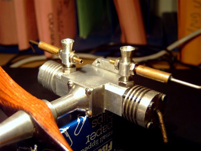
Many readers of these pages will be familiar with the name Mark Lubbock through his ML Midge, an engine designed for first-time engine builders that has been successfully reproduced all over the world. One glance at the Midge and the heritage of the Dragonfly (no relation to the other Dragonfly) becomes apparent--it's two Midge cylinders coupled to a common crankshaft in the usual way that staggers the cylinders to produce a simultaneous firing twin (Ron's eys begin to light up). Mark sent the pictures to Model Engine News and it would be best to repeat his description before launching into my own gratuitous observations.
Description (by Mark Lubbock)
 The engine is based on Midge .8cc cylinders with a three piece crankshaft. The front one is per the Midge design, but with the crankpin extended to 6mm long, and the diameter increased to 4mm. The rear shaft is the same, except the shaft length is shorter to suit rear bearing. The shafts are joined by pressing them together in a simple 3mm thick disc as a central crankweb, with the conrods in place. The completed assembly is trued up by spinning it in lathe and applying some judicious tapping with a lead block until the shafts and webs run concentrically.
The crankcase is machined from solid. No drawings were produced. The cylinder axis were determined by measuring the crankshaft after assembly. The front cylinder is per the standard Midge from its front face; the rear was machined to suit the crankshaft. The rear face of the crankcase has slots machined either side of the circular rear opening, in line with cylinders. This allows the shaft and conrod assembly to be inserted with the conrods at BDC. When the shaft is rotated 180° to TDC, the conrods clear the case deck, allowing the pistons to be dropped on and the gudgeon pins to be inserted. I have filled the slots with Paxolin 'slugs' to retain primary compression, but there seems to be no appreciable difference in running without them. These assembly slots in the case are sealed by an extended backplate/mounting ring which also carries a bronze bearing for the rear shaft.
Unlike the standard Midge, the front housing bolts onto the main crankcase. It extends into case as per the standard Midge and allows a little crankshaft end-float (a little wiggle!), set by backplate. I've been thinking that a bolt on case front could be a useful Midge mod to save machining. I know in theory it doesn't need 2 carbs, but I think it looks better!!
 The engine performs very well, being very smooth and easy to start. In fact, it handles just like a Midge! the single prototype has had a lot of work in a Solartex covered, 2 channel radio controlled Veron Deacon (52" span, 2 lbs flying weight) which it flies just adequately, but with little excess power. The only disappointing thing about it that as a simultaneous firing twin, it sounds just like a single.
To anyone anyone who fancies building one, I would recommend making a Midge plus two extra top ends as ready run-in cylinders for the Dragonfly. This makes starting the twin much easier as the running settings for the contra-piston are found while running-in the piston/liner assemblies (and you end up with a Midge as well!).
The engine performs very well, being very smooth and easy to start. In fact, it handles just like a Midge! the single prototype has had a lot of work in a Solartex covered, 2 channel radio controlled Veron Deacon (52" span, 2 lbs flying weight) which it flies just adequately, but with little excess power. The only disappointing thing about it that as a simultaneous firing twin, it sounds just like a single.
To anyone anyone who fancies building one, I would recommend making a Midge plus two extra top ends as ready run-in cylinders for the Dragonfly. This makes starting the twin much easier as the running settings for the contra-piston are found while running-in the piston/liner assemblies (and you end up with a Midge as well!).
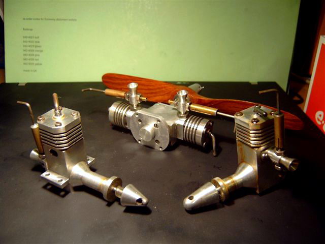
The single cylinder engine on the right in the photo above was born of needs when I built an R/C Moth for the Midge which turned out to be underpowered. I looked to see what I could do with it to increase power and retain the same mountings. The bore was increased to 12mm, the max the crankcase would take by moving the cylinder forward slightly. The crank pin was increased in diameter to 4mm and a larger carburettor flange mounted (no meat left for a thread!) with the port sizes increased and a ball-race fitted to the shaft. This gives a capacity of approx 1.2cc. This engine (the Midge Major) started 2nd flick from new and produces almost double the power of a standard .8cc Midge.
The other single cylinder engine is an as-yet un-named rear disc valve design. It is similar to the Midge Major, but with the three ports replicated on the other side to give two exhausts and four transfers. A Paxolin disc with timing pinched from the ED Racer and a lot of milling produce the beam lugs. This engine is quite powerful, easily outperforming a DC Sabre on smaller (7x4) props and has been flown in a C/L KK Phantom.
This means my engines have been flown in F/F, R/C & C/L models! All of my engines are used as intended, hence their rather oily appearance. If I loose one (two to date!), or break one, I can always replace it. The first Midge was born partly due to me nearly loosing a much loved DC Dart and wondering how I could replace it (pre Ebay!) [...and the rest is history! (Ron)]
Observations
Me again--and many thanks to Mark for taking the time to be so open with us. Assembling multi-cylinder engines is a design trade-off challenge, especially at model engine sizes. On larger engines, the normal solution is to split the conrod big-end in some way, and use screw fasteners. If this results in bolts at the side, the crankcase volume and engine profile must be increased to accommodate their arc of rotation. And the designer is still left with the problem of how to get at the bolts to tighten and safety them adequately in the close confines of the crankcase. Other schemes involving straps have been tried, and even proven (ETW's Ladybird, and Dan Calkin's Elfs), but require very precise work.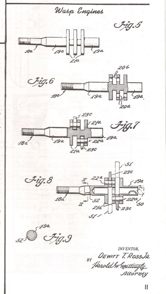
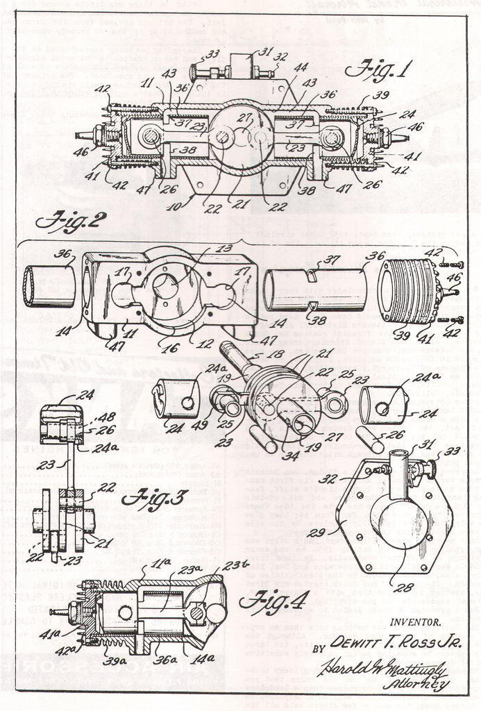 As soon as I read Mark's solution to the problem, I immediately saw a picture in my mind of an ancient patent application showing the details exactly as Mark described them. Knowing the application had been American led me to conclude that the location must have been in that magical resource, the Engine Collectors' Journal. Some searching found the material embedded in an article on the Wasp twins made by Dewitt T Ross Jr [1]. Dewitt and Mark had arrived at a similar engineering solution to the same problem, almost 50 years apart (note that the Ross patent offsets the conrods from the cylinder axis to place the cylinders in-line--precisely like a later and different "Ross" used thirty years later, but this time with split big-ends).
The down side is you are not going to replace the rods easily, or ever--but I don't think this is an issue. The other page of Dewitt T Ross Jr's patent shows his ingenious method of aligning the seven piece crank/rod assembly (as compared to the five in Mark's case (pun)). This one I have trouble believing in. Yes, it is ingenious and it will easily produce an aligned assembly without the pain Mark went through--right up to the stage where the central post is drilled out. My feelings and experience tells me that as soon as that drill tip breaks through a web and starts drilling on the tip with the drill shoulders un-restrained, it will deflect sideways, catch the hole in the web it has just drilled through and twist it out of alignment. The whole thing will probably hold together long enough to complete the operation, but it will have to go back into the lathe for truing up, so nothing much is gained except some additional white-knuckle time.
Conclusions
I gotta' build a Midge Twin (Dragonfly, whatever)!! Mark mentioned that he used twin venturi and NVAs rather than a manifold to "balance" the appearance. Since both feed a common cavity, with synchronized timing, adjusting either will affect both pots. A manifold could be worked out to make one thing less to fiddle with, but I think Mark's engine looks just right to anyone who has built a Midge, and it should stay that way!References:
| [1] | Chase, Randall: Development of the Wasp Engines, Engine Collectors' Journal, Volume 6, Number 28, Issue 4, Summer 1968, p13. |
![]()