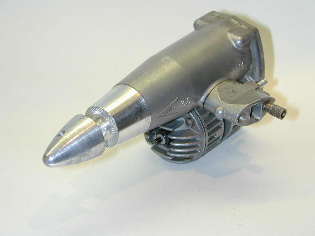
Aero 35 In-line Piston Engine
 |
 |
 |
| Name | Aero 35 | Designer | John Piston and Auggie Savage |
| Bore | 0.812" | Stroke | 0.670" |
| Type | Glow Plug | Capacity | 0.347 cuin |
| Production run | ~1000 | Country of Origin | USA |
| Photo by | Ron C | Year of manufacture | 1963 |
Background
The world of model engines has several noteworthy failures. These engines, while conceptually advanced for their time, were seldom great performers. The Morton M5 five cylinder, four-stroke radial is one; the horizontal piston Aero 35 is unquestionably another. I can relate to why it failed in the market. I was a high school senior when it appeared (or "sixth former", to be more culturally accurate). Like my model making school friends, I read the reviews in US magazines American Modeler [1] and Model Airplane News [2], plus the English ones, the Aeromodeller [3] and Model Aircraft [4][5]. While we were all wow'd by the styling, we were savvy enough to look at the performance figures and price, and conclude that our limited funds would be better spent on a Johnson 35 Stunt Supreme, or even an OS Max! Sadly, that pretty much sums up the collective reception of the modelling world. By the end of 1964, the Aero 35 had disappeared and the stage was set for Yet Another future "collectable" to wait for its real time to arrive.
 The engine's first public appearence had been in the June '63 issue of MAN with a full page display ad. The magazine reviews followed. Look at the publication dates of those four references. Wild Bill Netzbeand's was the first, appearing in the September/October issue of American Modeler (one L). The Brits were next with Chinn and Warring's reviews both appearing respectively in the "Christmas Special" issues of Model Aircraft and the Aeromodeller (two L's). Chinn's MAN review appeared in the January 1964 issue. Great coverage and clustering to die for, right on a peak buying period. But note the price. US$34.95 for the standard C/L "stunt" engine. In the same issue, World Engines listed the OS 35 Max III for $11.95. AHC had the Johnson 35 "Special" for the same price and the 35 Stunt Supreme for $14.95. Fox listed their 35 Stunt at $15.95. Not that the engines can really be compared. Aside from the unorthodox layout, the Aero 35 had twin ball races and the piston was fitted with two compression rings. The others were plain bearing with a lapped piston/cylinder fit. However they were cheaper, lighter, and more powerful.
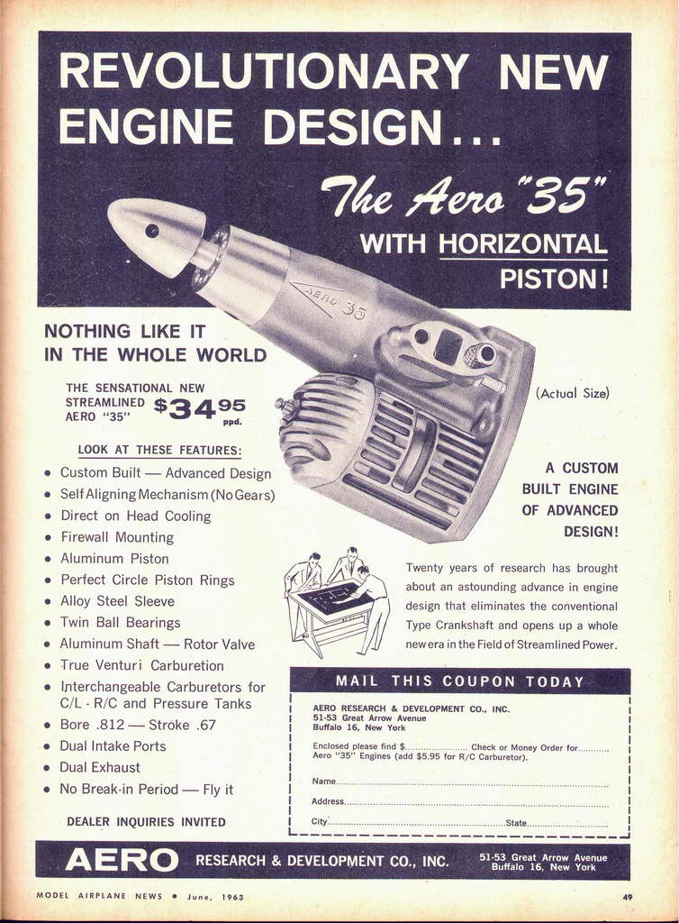
Incidentally, note the bullet points of the '63 ad that claims Dual Intake Ports; Dual Exhausts. This must have made Piston and Savage cringe. While the engine does have twin exhaust ports, it has only one intake port. It does however have dual transfer ports. Gotta watch those ad agencies.
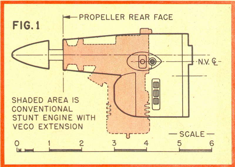 Despite the price disadvantage commented on in the British magazines only, all the modelling press raved over the engine, Chinn raved three times and I can find almost no sign of replication in the text of his two Atlantic spanning reviews. This is quite a feat when searching for words to explain a totally new concept! The side view drawing from American Modeler shows a Fox 35 with shaft extension for comparison. The height reduction is about 20%; significant, but notice that the engine is considerably longer. Price aside, the weight difference is the killer. The Aero weighs 10.6 ounces. Compare that to 6.5 ounces for the Fox, or 7.5 for the Johnson SS. Bolt that onto the firewall of your stunter and you have a bad center of gravity problem requiring tail weight. Move the firewall back and you've got a tank accommodation problem. Going to look great though. Oddly, not one of the reviews comments on this rather obvious fact. Maybe they wanted to like the engine. Then again, editorial policy towards advertisers may have been a factor too.
Description
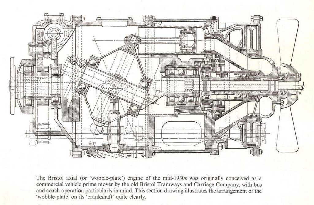 As we'd expect, Chinn concisely summarized the horizontal (aka "axial") piston design options, namely swash-plate, wobble-plate, and cam-plate. He concluded that the engine was none of these, the closest being the wobble-plate. As seen here in a Bristol design from the 1930's, the wobble-plate concept is based on an inclined section of a full crankshaft that carries a "spider" which is prevented from rotating, causing its tips to wobble back and forth as the shaft rotates. Each finger of the spider is connected to a piston by a rod with ball joints at each end. In operation, each rod will describe a figure-8 as it reciprocates. Presumably, the commonality Chinn saw to the Aero was the conical path described by the rotating component. Chinn described the reciprocating to rotary motion translation mechanism of the Aero as being achieved through a "L" shaped connecting rod. Netzeband used the same term, while Ron Warring referred to it as "T" shaped. Of all the descriptions, Warring's was the most detailed and best illustrated.
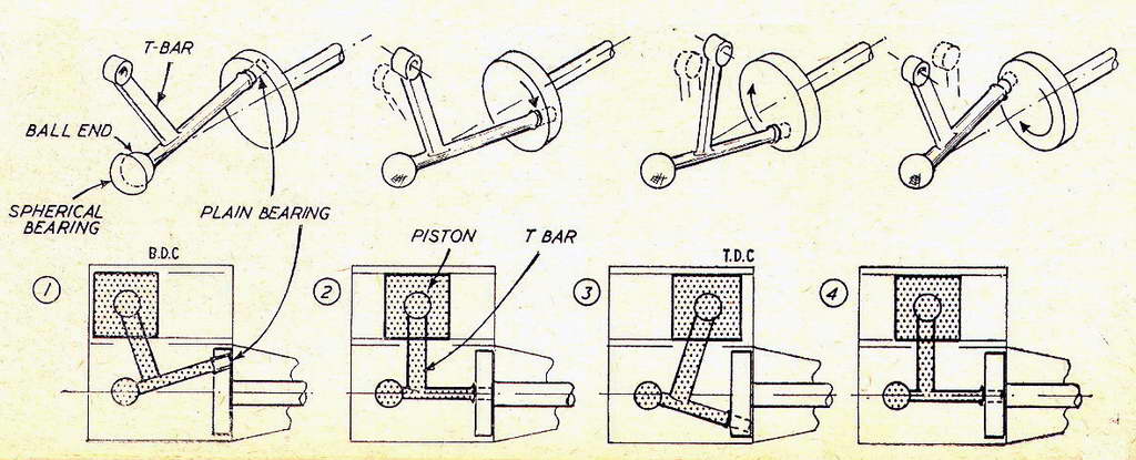
He starts by simplifying the internals to a T shaped rod showing how moving the cross-piece of the T in a cone angle will cause the bar of the T to adopt a reciprocating motion, pointing out that the end of the extension must also rock, side-to side. Note that in number (3) above, the bar of the T has magically stretched a bit to keep the "wrist pin" location in the middle of the piston. Also notice how the simplification would require a slot in the liner side for about 3/4 of the length in order to reach TDC. Not good for obvious reasons.
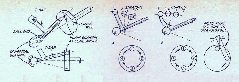
The next series of sketches shows how simply mutating the T to an L may reduce the length of the slot required for the extension motion, but has a negative effect on the path described by the end which must connect to the piston (A). Sketch (B) shows the answer: curve the extension so its end is behind the apex of the cone when at BDC and we can equalize the end displacements over the limits of its travel. This is what designer, John Piston, had achieved through 45 prototypes and 20 years of development [1].

Aeromodeller's last set of drawings depicts the actual mechanism. The end of the arm is going to want to move in three planes. While it reciprocates, it rocks side to side and nods up and down. To accommodate this, a form of universal joint is required. Warring described this as a "plunger little-end". As seen in the lower left sketch above, a circular block is pivoted on the the end of the arm. It is a close fit in a "C" shaped channel in the piston and slides up and down relative to engine orientation to accommodate the path described by the end of the cranked-L rod as it moves back and forth. That's two planes of motion taken care of. The third is accomodated by allowing the piston to rotate slightly clockwise (viewed from the rear) on the compression stroke, reversing on the power stroke. This is not as bad as it seems as the piston is fitted with two compression rings which will probably not rotate at all. Normal ringed aluminium piston clearance (about 0.002") means the piston is actually riding on an oil film, so the extra friction from this motion will be low. Netzeband called the plunger a "pillow block" which probably a more descriptive term.
The final sketch also shows how the web of the crankshaft can be cut-away to provide counter-balancing and act as a rotary inlet valve. Very, very neat. It is truly a shame that the designer did not receive the acclaim, in the shape of sales, at the time that he most richly deserved.
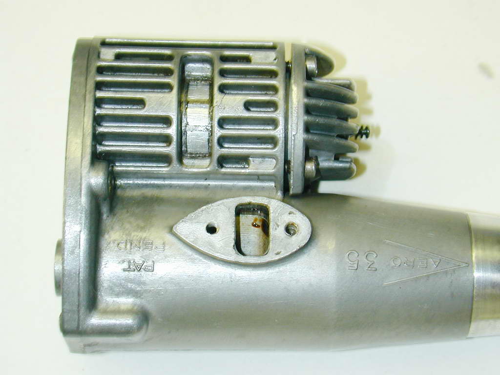
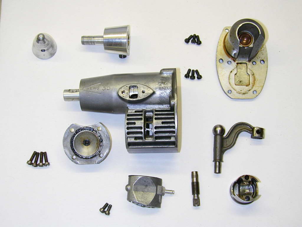 The engine is very well made. The crankcase is a very clean die-casting, with the cast iron liner cast in. It carries two ball races that support an aluminium crankshaft (and why not, given the loads involved) with a aluminium prop driver attached by a single grub-screw against a flat on the shaft. The driver also carries the threaded extension (UNF 5/16-24) for the streamlined spinner nut. The head, another pressure die-casting with a truncated cone shaped combustion chamber, is attached by only four 4-40 screws. Note that the gasket on my example, bought on eBay, has well and truly decomposed. The gasket is rather thick, so a new one was cut from 0.010" gasket material and good, bouncy compression was restored.
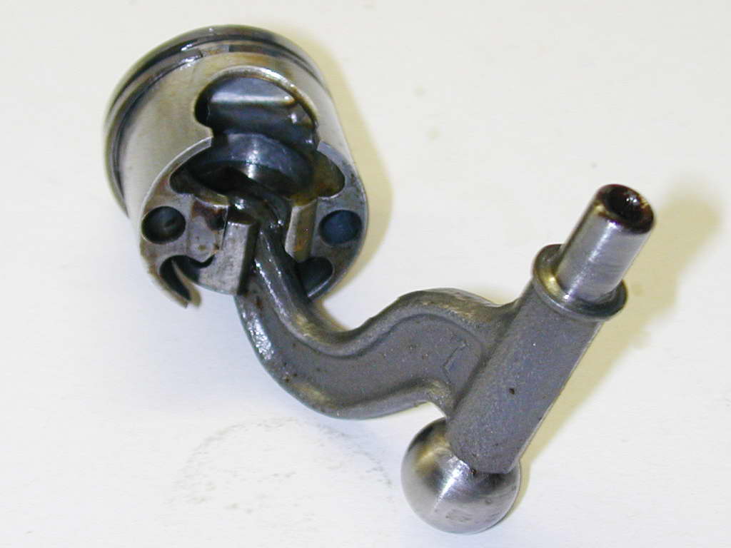 This shot shows the cast and machined piston with the slipper-block in place. The piston has been allowed to fall away 90° from its normal orientation to show how the block rides in piston. The conrod itself is a steel forging. The parallel shank of the rod rides in a bronze bushing pressed into the aluminium crankshaft. The piston has a definite top and bottom: one end of the "C" shaped channel the slipper block rides in has the corners milled away to clear the rod as it rocks side to side. Incorrect assembly is going to result in a tight spot followed by unexpected metal fragments. For reference, the orientation is this posed shot is exactly wrong!
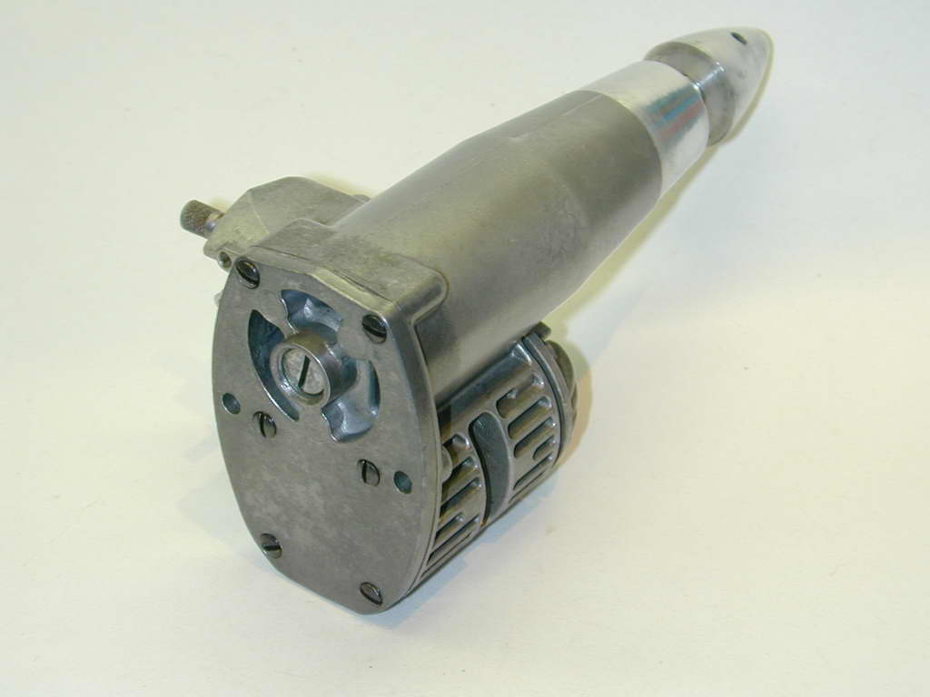
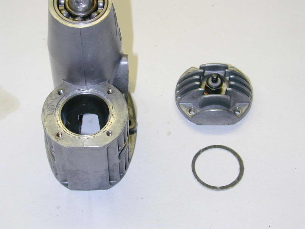
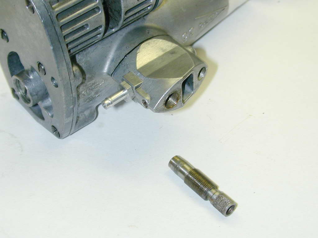
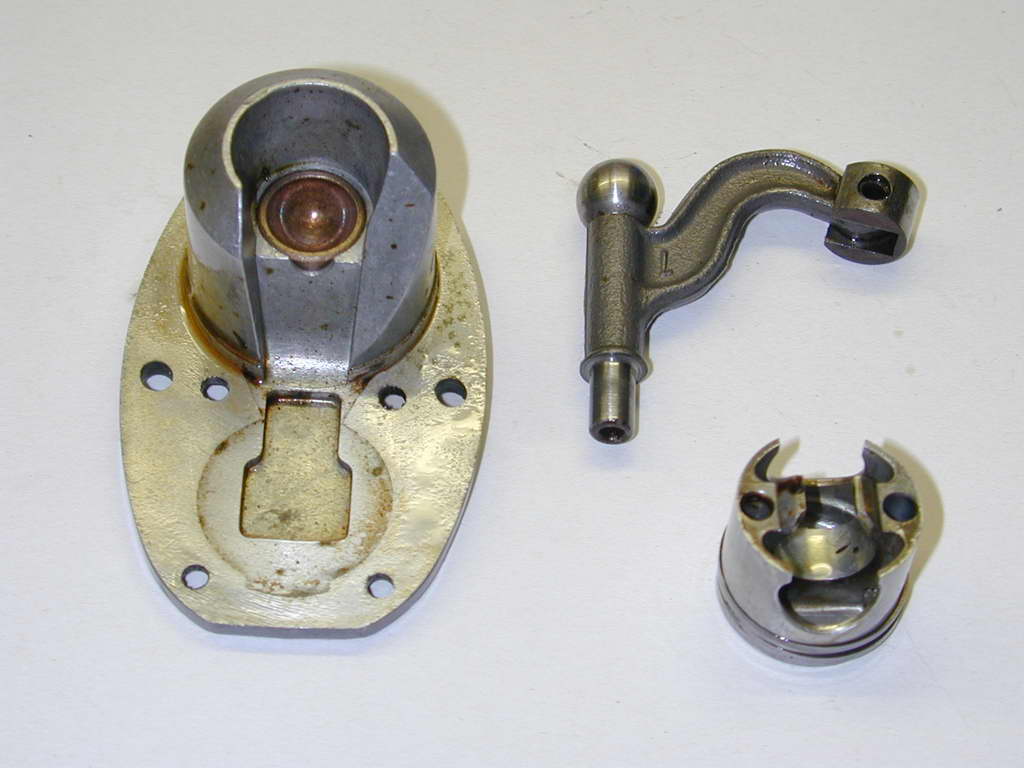 The backplate casting carries a sintered bronze socket for the conrod ball to rotate in. This rests against a set-screw in the rear of the backplate that is adjusted to correctly position the apex of the cone to take up excess free-play and wear in the bushed end (screw in until it stops, then back-off 10-15°). The backplate protrusion into the main crankcase minimises the cavity volume to provide primary compression. It is cut-away for the rod and to provide the gas passage to the bottom transfer passage formed by the lower cut-away section of the liner and a cast-in channel in the bottom of the case. The upper channel which provides passage for the conrod arm is extended to the same length forming another, opposed transfer port.
 Notice that while the gasketless backplate is attached by six 4-40 screws, the engine is mounted by only two screws. The holes for these clear 6-32 screws and are positioned to roughly distribute equal mass above and below. Note also that the mounting surface is not flat. Apart from the cup adjusting screw boss, all the attachment screw heads sit proud of the surface. The bulkhead would need to be dimpled appropriately. Aero Research said the engine was virtually vibration free. This is not so. The vibration due to reciprocation has been rotated 90° and it will produce a rocking couple centered pretty much on those two lonely mounting screws.
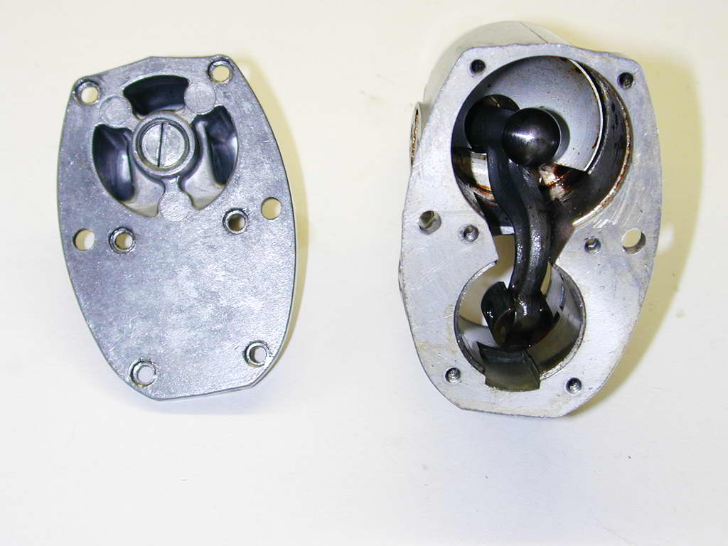
 The cooling fins of the crankcase run longitudinally, although getting air movement in them would be more due to turbulance than air-flow. Mostly, they seem to serve only to increase the surface area. However, the slots they form register aesthetically with the transverse fins on the cylinder head, and this would certainly be well cooled. Given the intimate contact provided by the cast-in cylinder liner, thermal conduction from rings to liner to case would most likely provide good heat dissipation. This photo also shows the size of the cut-out required in the upper part of the liner to provide passage to the rocking and twisting rod as it does its cone-dance.
 In this photo, the shaft has been rotated to the point where the inlet valve is about to close. The registration of even the radius of the cut-away crankweb matches the inlet opening perfectly. Although this would add very little to the required purpose, it highlights the attention to detail evident in the design and implementation. The exhaust ports punched in the liner have narrow posts to provide full support for the dual ringed piston. Some very neat casting and machining restricts actual contact between the crankweb and the inlet port to a narrow band around the latter (with oil film, there is probably no contact) minimising friction and wear.
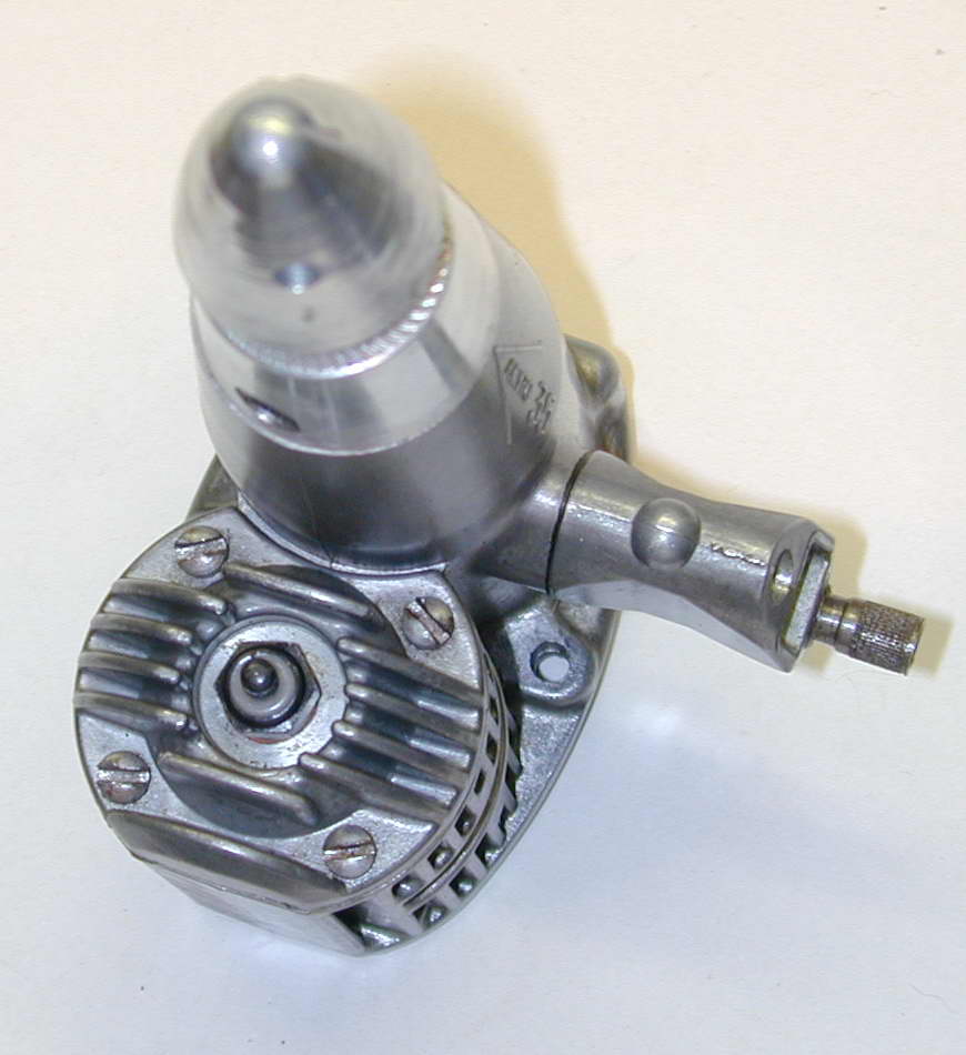
 The venturi and needle valve assembly is another unorthodox design. The streamlined carby casting has a rectangular opening with rounded corners. The casting is chamfered to angle inlet slightly into the air stream. The passage tapers and transforms to a 3/16" circular venturi neck, then expands back to a rounded corner rectangle at the crankcase flange. A fuel jet is drilled from the rear at the venturi throat, in line with the rear mounted fuel nipple. Fuel flow to the jet is controlled by a very large diameter, threaded stud with a slight taper on the inner end. The thread is 1/4-56 (!) and the cavity it screws into forms the counterbore for the rear carby mounting screw. As another indication of attention to detail, a tiny, rear facing grub screw presses a nylon pad against the needle thread to provide adjustable friction. The same casting was used the R/C carby which inserted a restricting slide through a hole drilled in the domed protrusion seen at the front of the venturi casting.
Conclusion
Chinn's reviews state that he tested it on a dynamometer where it recorded 0.42BHP at 11,500 rpm with 5% nitro. This, he says, is 20% below a "typical, modern" stunt 35 on the same fuel [2]. Aeromodeller's curves show a peak of 0.40BHP at 12,800 rpm [3]. I really must mount this thing and run it someday, just for fun. The engine has twin, opposed exhaust ports and the engine geometry precludes any way of fitting a silencer (we wanted more noise in the 60's, not less!) This largely rules out ever flying the thing today, and as noted earlier, it would either require a special airframe, or so much tail weight that stunt performance would be impacted. So it will probably continue to sit on the shelf as a tribute to a designer who though outside the box, and suffered the usual fate for it.References:
| [1] | Netzeband, W: Horizontal Piston Engine, American Modeler, Condé Nast Publications Inc, NY USA, Volume 60, Number 5, Sep/Oct 1963, p18. |
| [2] | Chinn, PGF: Engine Review . AERO .35, Model Aairplane News, Air Age Inc, NY USA, Volume LXIX, Number 1, January 1964, p28. |
| [3] | Warring, RH: Engine Analysis No 117: AERO 35, Aero Modeller, Volume XXVIII, Number 335, Model Aeronautical Press Ltd, GB, December 1963, p612. |
| [4] | Chinn, P: Latest Engine News, Model Aircraft, Percival Marshall & Co Ltd, London GB, Volume 23, Number 270, December 1963, p348. |
| [5] | Chinn, P: Latest Engine News, Model Aircraft, Percival Marshall & Co Ltd, London GB, Volume 23, Number 271, January 1964, p20. |
| [6] | Dannels, T: Engine of the Month "Inline Singles" Engine Collectors' Journal, Model Museum, CO USA, Volume 8, Number 6, Issue 42, May/Jun 1972, p2. |
![]()
