The ED Baby
Reproduction Project
Page 2
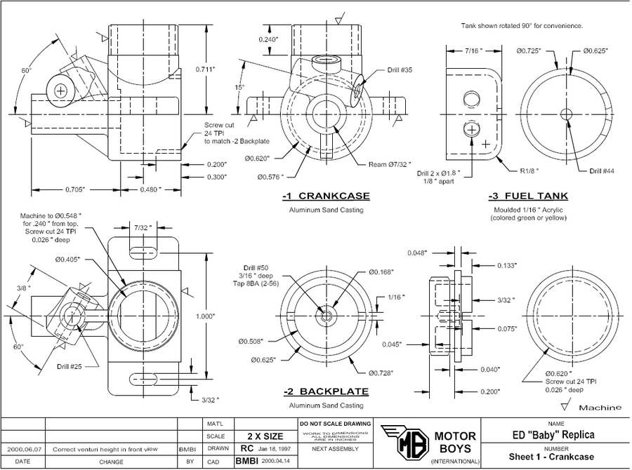
In this part, we move onto the crankcase and backpate. These appear on Sheet 1 of the drawings as parts -1 and -2 respectively. Experienced model engine builders will know how spending an hour making a jig that will only be used for ten minutes actually makes sense when the alternative is the high probability of a catastrophy due to work holding difficulties.
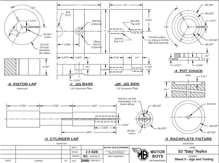 Sheet five shows some fixtures that will truly simplify machining of the parts on sheet one. You could manage without them, but life will be rather more enjoyable with them! A breief note on 5-1 (the crankcase holding fixture base). Since space was short on the sheet and the part is symmetrical around the centerline, only one half of the part is shown. It requires two -2 Side Plates, but as these are identical, only the right hand one (-2R) is drawn. This should be obvious, but is worth mentioning anyway.
- Part:
- 1-2 Backplate
- Prerequisites:
- Nil.
- Things to Watch:
- Check each set-up to see that front and rear machined surface are concentric and parallel.
- Tooling Required:
- Sharp corner knife tool, 55° included angle external thread form tool (or 60° for US thread form), 0.040" wide parting tool, #1CD, #50 twist drill, 8BA (2-56) second and bottoming taps, 1/16" slitting saw and arbor.
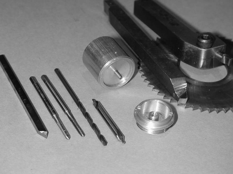
Holding Fixture 5-5 (Optional)
Turn a jig from a stub of scrap �"D bar stock about 3/4" long, recessed centrally to the OD of the tank rim for 1/16" deep. The stub is then drilled through #43 to clear an 8BA (2-56) screw that will secure the casting in the central recess.
Procedure:
- Place casting in 3JSC chuck, concave side towards the tailstock with about 1/32" of the major diameter protruding. Square the casting to run relatively true by aligning it against a steel rule placed over the tip of the tailstock barrel.
- Skim the OD of the fuel tank locating rim to 0.625"D and face the area behind it square until the casting just cleans up. Make a face cut on the 0.625"D rim until it is .085" wide. Lightly chamfer this rim at 45 .
- Face the central tank bolt spigot until it is 0.093" below the rim. Drill with #1CD, then drill #50 to a maximum depth of 3/16".
- As a safety precaution, remove power from the lathe, then place an 8BA (2-56) second taper tap in the tailstock mounted drill chuck and begin tapping the spigot, rotating the lathe chuck by hand. Follow with a bottoming tap. If you wish, you may lightly skim the interior of the casting to a smooth finish, although this is by no means necessary.
- To make the slot used to tighten the back plate into the crankcase, transfer the chuck to the rotary table, set vertically under the mill and mount a slitting saw of about 1/16" thickness. Lower the saw until a tooth just touches the tank mounting rim. Zero the vertical feed dial, then lower by one half the sum of the rim OD and saw thickness. This will position the saw for a cut across the rim diameter. Make a transverse cut of about 0.010" shallower than the rim height. Alternately, this cut can be made with a 1/16"D end mill (holding the backplate in a milling attachment) or even with a hacksaw and needle files.
- To form the thread, the backplate may now be reversed in the 3JSC chuck and gripped by the tank locating rim. This is a rather delicate setup, so you may prefer to make the 5-5 Backplate Fixture.
- Turn down the casting to �"D overall, then reduce the length to 0.248" as measured from the turned face at the rear of the part. Fit a narrow parting blade with a tip width of 0.040" (this will be used again for the cylinder head fins) and position it 0.048" from the left face of the part. Make a cut 0.09" deep. This groove provides a run-out area for the thread cutting operation that follows. Now reduce the diameter down to 0.620"D over the length to the tailstock side of the groove.
- Set up to cut a thread of 24TPI (you may use 32TPI if you wish). The original engine used a thread form with a 55° included angle to the British Whitworth specification. You may choose to use the more common 60° included angle form. Whichever, the tool should have minimal material to the left of the point so that the tip enters the run-out groove without striking the back plate sealing face. Run the lathe in slow back-gear to allow yourself time to react and cut the thread 0.026" deep (or 0.019" deep for 32TPI).
- Part:
- 1-1 Crankcase.
- Prerequisites:
- 1-2 Backplate; 3-4 Venturi Insert (optional - see Things to Watch).
- Things to Watch:
-
The cylinder liner bore must be precisely at right angles to the crankshaft bore. The liner seat must be at right angles to its bore and 0.711" above the crankshaft bore axis. This bore should be reamed and finished as smoothly as possible.
Fitting of the 3-4 Venturi insert must be left until last as it would interfere the cutting of the external thread for the cylinder head. Optionally, this part may be omitted altogether and the intake hole in the casting drilled #33.
When using the 3-4 Insert, the procedure described requires that the crankshaft bore be reamed twice. First without the insert, then with. The 2nd time, with the insert, if the metal to be removed from the insert is too great, the reaction force from cutting the insert end will also remove metal from the bearing bore on the opposite side from the insert. The bottom of the insert can be carefully profiled with a needle file to within say 0.003", but this runs the danger of the file scoring the bearing surface.
If you prefer, the venturi boss may be faced (step #26), the venturi hole drilled (step #21), and the spray bar hole drilled (step #28) first while the chucking boss is attached. Then the insert can be temporarily secured in position with a bolt thru the spray bar hole when the bearing is reamed the first time.
- Tooling Required:
-
Sharp corner knife tool, small "L" shaped boring tool, 55 degree included angle internal and external thread cutting tool (or 60 degree for US thread form), #1 and #2CD, twist drills, 7/64" hand reamer, 3/32", 1/4" and 1/2" slot drills, odd leg ("Jenny") callipers and center punch.
Crankcase Jig (5-1, 5-2R, 5-2L)
Note: This jig can simplify work-holding for drilling the venturi and spraybar holes. Use of this jig to machine the cylinder area assumes that the bottoms of the mounting lugs have been machined parallel with the CL of the casting. If you cannot do this, do not use the jig to machine the cylinder area. Instead, bolt the case to an angle plate. This assures squareness of the cylinder liner bore to the case bore.The jig is made from 1/4" plate as shown on Sheet 5. The following procedure assumes use of the jig, although as noted above, the traditional method of bolting the crankcase to an angle-plate attached to the lathe faceplate can also be used.
The slots in the 5-1 Base should be milled at right angles to one edge. The two side frames (5-2L and 5-2R) as shown on the drawing are securely attached with 4-40 socket head screws. After assembly, the top of the side frames must be milled parallel with the base, or turned true on the lathe faceplate.
Procedure:
- Smooth the rear and top of crankcase where it will be bored with a fine file. Carefully establish the center of the each with odd-leg callipers and lightly center punch. These are important references; work as accurately as possible.
- Mount crankcase in 4JI or 3JSC chuck by front chucking stub and adjust until rear center punch mark runs true. Do a final check with a dial indicator on the casting OD. Do not disturb this setting until all axial work is complete.
- Transfer chuck to rotary table mounted vertically under the mill. Orient with cylinder vertical and adjust until the top both lugs are about the same height above the mill table. Locate the mill axis over the marked cylinder bore center and zero both dials.
- Rotate crankcase by 180 degrees and face bottom of lugs smooth and parallel to the chuck axis with a �" slot drill, cutting into curved crankcase so that the width is 0.750", symmetrical around the established center.
- Drill each end of the mounting slots 0.500" either side of center and 0.109" (7/64") fore and aft of center. Mill out the slots carefully with a 3/32" slot drill. If you try milling the slot in one go, the case will probably flex and the slots will appear to be at an angle to the axis.
- Return the chuck to lathe and mount a drill chuck in the tailstock with #2CD; center drill, then drill through #8. Follow with �" drill, drilling 7/16" deep only.
- Rotate until cylinder is facing operator. Mount a sharp pointed knife tool and position tip precisely at the center punch mark of the cylinder bore. Lock the saddle, zero the compound slide dial, then move tool tip 0.300" towards tail stock. This is the aft face of the case. The tool should just clear the cylinder at this point. Now move tool tip rearwards, clear of the work.
- Now begin facing back the crankcase with the mounted knife tool taking cuts of no more than 0.015" per pass until the 0.300" reading is reached.
- Mount a 1/2"D slot drill in the tailstock and carefully drill into the crankcase until the cavity is exactly 0.480" deep as measured from the rear face.
- Mount an "L" shaped boring tool with a tip width of about 1/8". Bore the internal cavity to 0.576"D overall. This is the diameter to be threaded for the 1-2 Back plate.
- With the same tool, open out the forward interior of the cavity to 0.620"D from the thrust face for a total distance of 0.280"
- Open out crankshaft bore with a #4 drill, then lightly countersink the hole edges to allow for the transition radius of crankshaft.
- Switch off and remove power to the lathe. Mount a 7/32" hand reamer in a tap handle and enter its tapered section into the bore. Bring up a dead center in the tailstock to press against the end of the reamer and commence reaming, using kerosene as lubricant, turning the chuck by hand, applying pressure via the tailstock and resting the tap handle against the lathe saddle to prevent rotation. Withdraw the reamer every 1/8" or so to clear the chips, always rotating the work in the "forward" direction. This process is known as "floating" the reamer and produces the optimum smoothness and roundness for amateurs. Continue until at least 1" parallel depth is achieved.
- Set up your lathe to cut a 24TPI thread (or 32 TPI if you chose) to match the thread in the 1-2 Back plate. Choosing a thread that is a multiple of the lead screw pitch (mine is 8TPI) means the half nuts may be engaged at any point,
- With lathe in slow back-gear, cut the thread to approximately 0.026" deep (or 0.019" for 32TPI), increasing depth by no more than 0.002" per pass. As full depth is approached, reduce to 0.001" per pass and make repeated passes at the same depth to allow for tool spring-back.
- As full depth is approached, generously oil the 1-2 Backplate thread and check the fit into the female crankcase. The oil is needed as tight, dry aluminium threads will easily weld themselves together - very nasty! The correct fit is achieved when the 1-2 Backplate can be screwed in by hand with positive, but light resistance.
- Mount a parting off blade and touch the left side to the rear of the case. Advance the tool 1.184", plus the width of the blade itself. Mount a stub of round material in the tailstock chuck and advance it into the crankcase cavity to catch the case as it is parted off, then part off from the chucking stub.
- Mount the crankcase in the jig fixture and clamp it to a lathe faceplate using a "wobbler" and DTI to center the crankcase over the center punch mark on the top of the casting. Check the centering with an indicator on the casting OD.
- Rotating the work at about 300RPM, drill with a #2CD, then drill through into the crankcase bore with a 1/4" drill bit. Take a facing cut across the top of the casting to ensure a flat surface, normal to the hole just drilled.
- Press a length of 7/32"D drill rod into the crankshaft bore and measure the depth from top of casting to the top of the rod. Calculate the amount of material to be removed so that the top of the casting will be precisely 0.711" from the axis of the crankshaft bore (0.602" above the rod surface). Face down to this height taking light cuts and frequent measurement.
- Mount a sharp knife tool and reduce the diameter of the casting to 0.548"D. Try to achieve of 0.230" from the cylinder seat before you run into the venturi boss. (It will help if the boss has already been faced - see step #26.)
- Mount an external thread cutting tool and set the lathe to cut 24TPI (again, increase to 32TPI if you wish). CAUTION! The length of thread to be cut is such that the tool may strike casting in the area of venturi top at maximum length of cut. Grinding a tool with minimal width to the left of the point reduces the chance of this. Be assured, it can be done!
- With the lathe in slow back-gear, thread the exterior to a depth of 0.026" (0.019" for 32TPI) over the full turned down length. Again start with 0.002" passes, reducing to 0.001" with several passes at the same depth near the final cuts.
- Open the bore out with a 3/8"D drill, then re-fit the "L" shaped boring tool and finish to an ID of 0.406"D and maximum depth of 0.500". The front of this bore will just cut into the thrust face. Alternately, use a 13/32"D slot drill for this step.
- Remove fixture from faceplate and transfer to the mill vice with the spindle centered over the cylinder bore. Angle the jig so that the crankshaft bore is 30° from the horizontal and move the work until a #1CD mounted in a drill chuck is over the top of the venturi boss area. Estimate the position for the venturi hole so it will intersect the angled needle valve assembly (NVA) axis. While this sounds imprecise, it is surprisingly easy to do! Now drill #25 and check for a smooth but free fit of the 3-4 Venturi Insert.
- Without shifting the set-up, mount a 1/4" slot drill or end mill and face the top of the venturi area to be about 1/32" above the low side of the NVA boss (see step #21).
- Check to ensure that the 3-4 Venturi Insert fully, but minimally protrudes into the crankshaft bore. Permanently secure the Insert into the crankcase with lock-tite, or a similar material. Carefully round the part protruding into the bore with a needle file taking care not to contact the bore itself. Finally, re-ream to blend the insert into the bore. If you try to remove too much material in this step, the bore will go egg shaped and the part becomes a paper weight. If in any doubt, drill #33 instead of #25 and omit the 3-4 Insert.
- Now mount the jig to drill for the NVA. Ideally, this will be 15° from the horizontal and angled back by 30°. It is important that this hole intersect the venturi bore as centrally as possible. I used a tilting vertical slide on the lathe saddle for this and again, eye-balled the alignment without difficulty and with very acceptable accuracy. Drill with #1CD, followed by #37 and #35 drills. Don't forget the hole will be #33 if the insert is not used.
- We want the overall length of the NVA boss to be 0.375", with flat faces normal to the holes axis and equally disposed about the centerline. So, while in this set-up, face the end of the NVA boss with a 1/4" end mill, guesstimating the amount of material to remove. Swap to the other side by rotating work and adjusting the angle so a drill bit cleanly enters the NVA hole. Face the remaining side of the boss and adjust to final length.
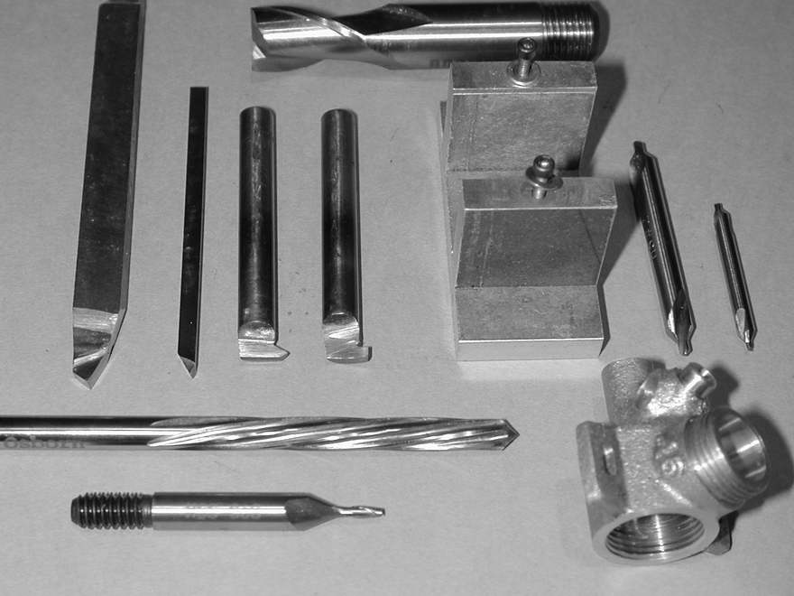
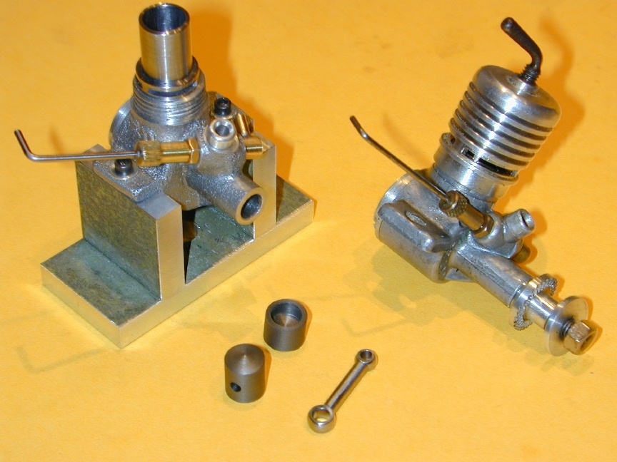 This photo shows a crankcase mounted in the fixture shown on sheet five. Using this jig on a faceplate to bore and face the cylinder seat requires that the underside of the lugs be aligned with the crankshaft bore. This requires machining while still held by the chucking piece. If you can't do this, holding the case in the jig will not be accuraye enough for the critical 90° alignment and you'd be better off clamping the case to an angle plate bolted to a faceplate using the machined rear face of the crankcase.
 But even if not used for machining the cylinder bore, the jig simplifies aligning the crankcase for srilling the spray bar hole as seen here (see Step #28 above). The tilting and swiviling vertical slide helps too, but the operation can be performed with shims and packing.


![]()
 Home
Home
This page designed to look best when using anything but IE!
Please submit all questions and comments to
[email protected]