Truely Strong Japanese Motors
by Adrian Duncan
Click on images to view larger picture.
No, we haven't succumbed to a fit of Glad Garbage Bag-inspired commercialism here—we're not advancing the claims of any particular engine as being more sturdy or powerful than the rest. We're speaking about a short-lived and now almost completely forgotten range of Japanese-made engines which appeared out of nowhere in the mid 1960's and then disappeared almost as quickly as they arrived, leaving little trace. These engines were marketed under the Strong trade-name, hence our title.
The Strong engines were manufactured for just a couple of years beginning in 1964. The manufacturers were Tokyo-based and traded under the name Strong Motor. The designer and company founder was reportedly a certain Haruo Shimizu san.
There's a certain feeling of being caught in a time warp when discussing the Strong range. This is because although these engines originated in the mid-1960's, their design reflects a far earlier period in model engine history. It's almost as if we're discussing a 1940's design that suffered extreme production delays and only made it onto model shop shelves in the mid 1960's! In this sense alone, the Strong engines are certainly among the most idiosyncratic creations of the Japanese model engine industry.
Let's begin by reviewing what little information is available in the English-language modelling media...
Background
By the mid 1960's, when the Strong range first appeared, the Japanese model engine manufacturing industry had completely overcome the early post-war stigmas under which it had initially been forced to compete in the International marketplace. As of 1964, when the Strong range appeared, the Japanese industry was rightly viewed as a world leader in terms of both design and quality and its products and activities were closely scrutinized in the English-language modelling media of the day.
This underscores the relative obscurity of the Strong range of engines now under discussion. Although the range appeared during the heyday of Japanese model engine production, it received scant coverage in the Western modelling media. It seems that neither the engines themselves nor any comprehensive information about them left Japanese shores in any substantial quantities. Even during its actual production period, this was an extremely elusive range outside Japan and time has done little to improve this situation. The present article won't answer all the questions, but it will hopefully represent at least a first step towards a better understanding of these intriguing engines.
The Strong range first came to the attention of modellers in the English-speaking world through an announcement in the regular "Motor Mart" column published in the July 1964 issue of Aeromodeller magazine. This article made very interesting reading indeed! The Strong range at the time of its introduction was stated to consist of glow-plug ignition crankshaft rotary valve R/C models in both .09 and .19 cuin displacements, as well as a pair of twin-cylinder models.
The twins were described as follows:
- A .40 cu. in. glow-plug ignition model using a pair of .19 cylinders on a common square-section crankcase which was fed by a downdraft carburettor; and
- A 10 cc in-line twin model featuring two .29 cu. in. cylinders located on opposite sides of a centrally-located disc valve induction system feeding both crankcases from a side-mounted carburettor. Most intriguingly, this model was specifically stated to be intended for spark ignition operation. It was apparently supplied with an exhaust collector manifold and a streamlined tank attached to the crankcase.
Most frustratingly, no images of any of these models were provided with the article. Imagination was free to run riot. we can only say that the description of the .40 cuin model makes it sound as if it was an opposed twin design given the use of a common crankcase for the two cylinders.
The next appearance of the Strong engines in the English-language modelling media came in the 1964 Global Engine Survey published by American Modeler magazine in their 1965 Annual, which went on sale around Christmas 1964. This survey was unattributed, but certain internal evidence strongly suggests that it was compiled by Peter Chinn. Indeed, at the time in question there could have been few if any other individuals in a position to assemble such a survey in a comprehensive and authoritative manner.
In the section devoted to Japanese engines, the 1964 Survey noted that a new range of engines had "recently" been announced in Japan under the name Strong. This is of course entirely consistent with the July 1964 Aeromodeller article to which reference has previously been made. It was stated that few details of these engines were as yet available, although the table attached to the article did include basic measurements for those models of which the writer had become aware.
Reference to the table in question confirms that the Strong engines were available in both .09 and .19 cuin displacements, just as reported earlier in Aeromodeller. All models apparently followed the same basic design pattern, with crankshaft rotary valve induction being a common feature. The .09 model reportedly had "square" bore and stroke measurements of 12.7 mm each for a displacement of 1.61 cc, while the .19 model utilized a bore and stroke of 16 mm each for an actual displacement of 3.22 cc. The .09 model was a plain bearing unit, while the .19 model was available in both plain bearing and twin ball bearing versions. This was as far as the writer of the survey was able to go in describing these engines—clearly he did not have actual examples on hand for examination.
Most strangely, there was no mention of the twin-cylinder models described earlier by Aeromodeller, nor did the American Modeler survey mention the existence of R/C versions of the .09 and .19 models which were included. It's possible that the twins were viewed as custom-built "specials" rather than as commercial productions like the other models included in the Survey.
Taken together, the above two references appear to authoritatively confirm 1964 as the year in which the Strong range first appeared. Thereafter, almost nothing further was heard of these engines outside of Japan. Certainly, they were never the subject of a published test in the English-language modelling media, perhaps reflecting the fact that they do not appear to have been marketed with any fervour or success outside of their native Japan.
In fact, the next published appearance of the Strong name came in the form of a retrospective reference which appeared in the March 1975 issue of Model Airplane News This was to be found in Peter Chinn's "Foreign Notes" column for that month and took the form of an illustration of one of half-a-dozen .45 cuin in-line twin-cylinder glow engines reportedly made by Mr. Haruo Shimizu under the name Strong 45 Twin during 1964-65. The relationship of this model to the .40 cuin unit reported by Aeromodeller in their July 1964 article is presently unclear. It could be either a concurrent production or a replacement—at present we have no way of knowing.
The only other English-language reference of which we are aware is David R. Janson's description of the Strong 45 twin which appeared as number 43 in Janson's series entitled Model Engine Designer and Manufacturer Profiles This very interesting series of articles was published over a period of years in the newsletter of the Denver chapter of the Society of Antique Modellers (SAM). A compilation of the entire series was released in small numbers as a private publication in 2006, and our friendly Editor was one of the lucky few to secure a copy!
Article number 43 in the series provided a few design details of the Strong 45 twin, which was a most interesting if somewhat fragile unit. The twin cast-iron cylinders featured very thin integrally-turned fins and screw-in alloy cylinder heads. These features were also seen on the Strong single-cylinder models, of which more anon.
In the case of the twin, the cylinders were bolted to the sandcast crankcase using a locating flange for each cylinder. Triple bypass passages were employed in each cylinder along with a single exhaust port. The exhaust was collected from both cylinders by a substantial extractor tube running fore and aft on the exhaust side of the engine. Twin disc valves were located between the two cylinders and were fed by a single R/C carburettor centrally located beneath the crankcase. The unit was completed by the addition of a streamlined back tank secured to the backplate.
It's noteworthy that apart from the displacement and ignition system, the description above very closely matches that of the spark-ignition .60 cuin model described in the July 1964 Aeromodeller article. It may be that the .60 was a one-off prototype upon which the 45 twin was based —we'll probably never know.
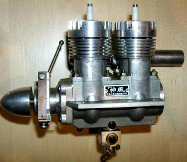
It's also worth mentioning in passing that an updated version of the Strong 45 twin was subsequently manufactured in very limited quantities in 1974-75 under the name Kamikaze 40. This fine engine was described in an article which appeared under Peter Chinn's "Foreign Notes" byline in the February 1975 issue of Model Airplane News This engine was produced through an initiative on the part of Akira Fujimuro and N. Morita, but the actual designer of the Kamikaze Twin was none other than our friend Haruo Shimizu, creator of the original Strong 45 twin and former manufacturer of the other Strong engines.
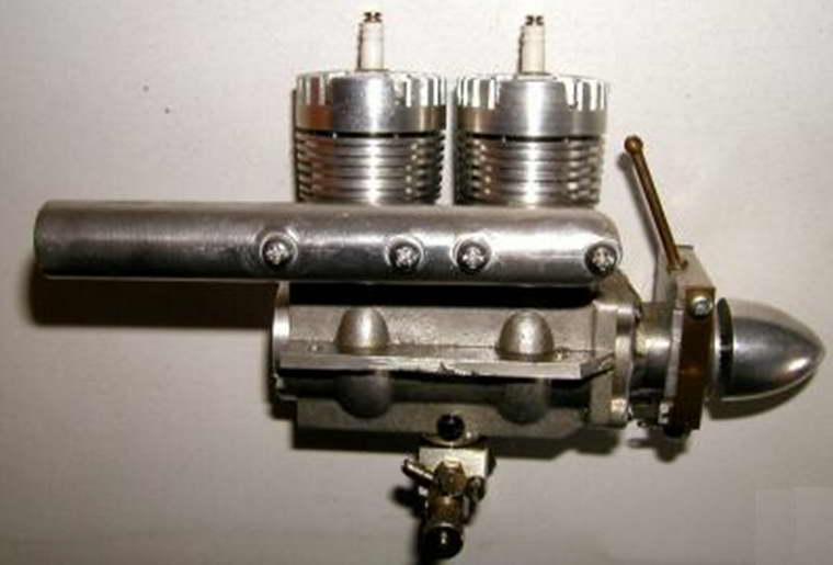
The Kamikaze 40 twin was very similar to the Strong 45 twin in terms of its general design but was far more robustly constructed and was manufactured using more up-to-date methods. We are fortunate to be able to include several images of this rare and memorable engine courtesy of my valued friend and colleague Alan Strutt of Somerset, England.
Returning to the Strong story, the twin-cylinder models mentioned above clearly fell into the "labour of love" category and could never have been expected to form the basis of a commercially-successful long-term involvement in the model engine industry. That role was doubtless delegated to the single-cylinder Strong models in the popular .09 and .19 displacement categories. It's therefore a little odd that despite the clear desirability of promoting these engines on the part of the manufacturer, we have so far been unable to track down any references other than the two 1964 articles from Aeromodeller and American Modeler noted above. As a result, there have up to now been no published descriptions of these engines in the English language
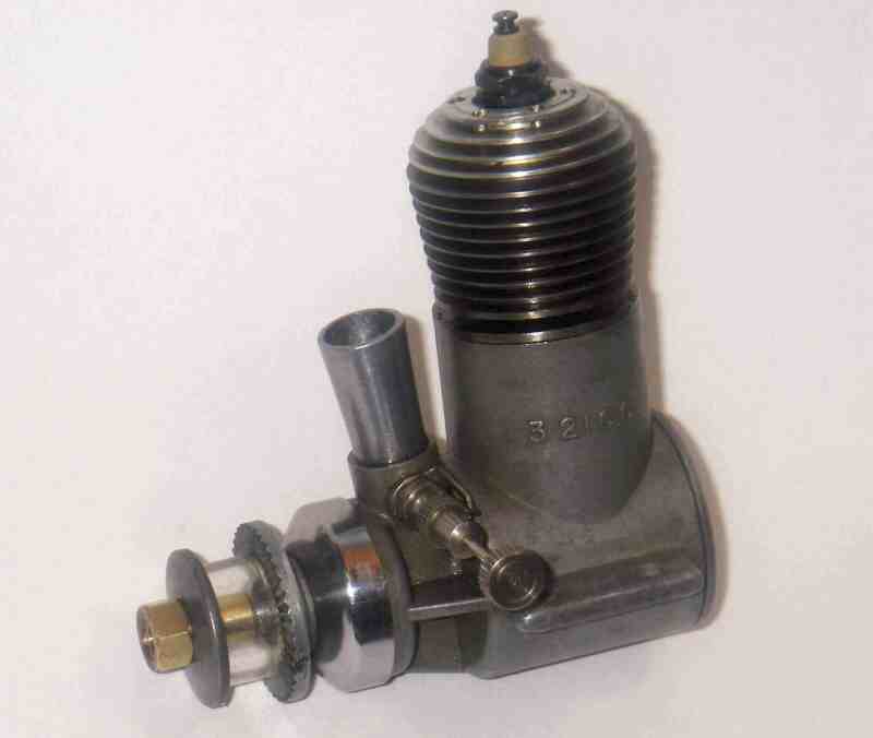
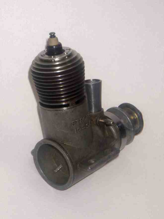
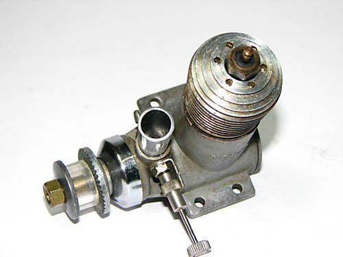
Fortunately, we are able to improve on this situation thanks to the fact that I'm lucky enough to own a fine near-new example of the .19 cuin ball race version of the Strong engine. Since the range never appears to have made it outside Japan in any quantity, examples are few and far between, at least in the English-speaking world—indeed, I've become aware that many of my collector colleagues have never even so much as seen a Strong engine! So having one here at hand, I felt that the least I could do was share it with my fellow aficionados to the best of my ability.
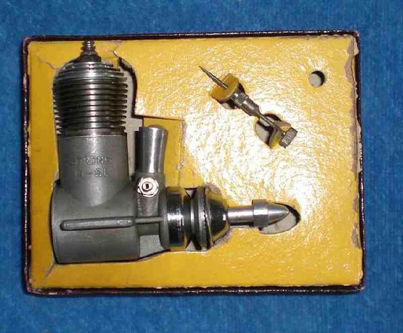
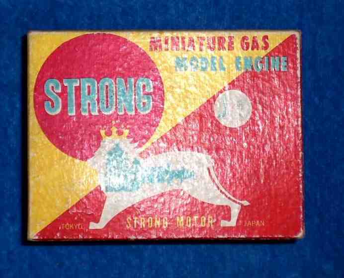
Contact with Alan Strutt revealed that he had a new-in-box example of the same engine, from which a little more information could be gleaned. Rather annoyingly, there's no instruction leaflet with the engine and no information on the manufacturers beyond the fact that they were based in Tokyo and gave their corporate name as Strong Motor. The engine is presented in an attractive red and yellow box with blue lettering.
Description
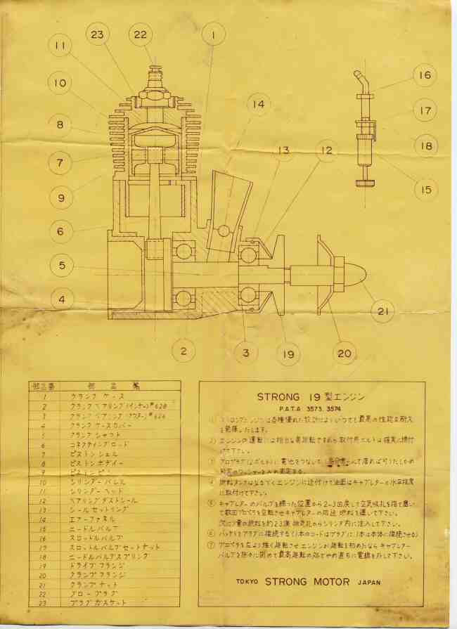
It's readily apparent right off the top that the Strong 19 shares several structural features with the 45 twin described by David Janson. We would of course expect this given the fact that both the singles and the twin were evidently designed more or less concurrently by Haruo Shimizu. The cast-iron cylinder with thin integral fins and a screw-in alloy head are obvious "house similarities". However, the construction of the single cylinder model is considerably simplified by the use of a screw-in cylinder rather than one equipped with a flange for attachment to the case using screws.
The first impression that one gets upon one's initial encounter with this engine is that it seems notably "old fashioned" by the standards of the mid 1960's when it was introduced. For a start, the engine uses radial porting in combination with reverse-flow scavenging. The use of this type of porting had long ceased to be fashionable for glow motors and by 1964, even such die-hard radial-port stalwarts as Fuji having largely abandoned the layout.
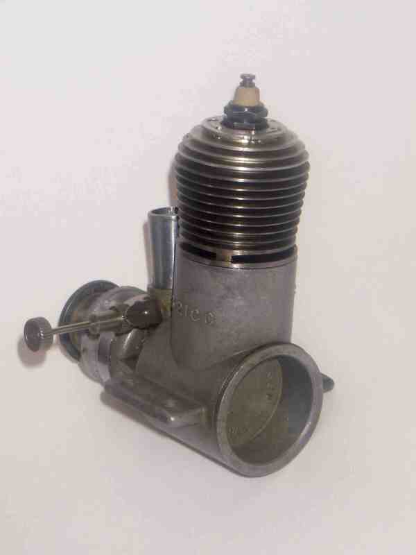
he Strong actually gives the impression of being a slightly updated variant of an Arden 19 glow model from the 1940's! This impression is heightened by the screw-in cast-iron cylinder with thin integral cooling fins and screw-in alloy cylinder head. The die-cast backplate is also of the screw-in variety. All components are fitted with gaskets to ensure a seal, with that under the cylinder head being of soft copper while the cylinder base and backplate gaskets are of fibrous material.
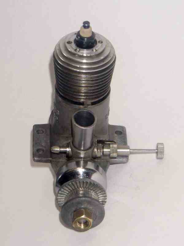
The short main bearing adds to the overall Arden look of the engine, the main obvious differences being the upright (as opposed to inverted) venturi and the absence of a tank. The venturi stack is a separate component that is retained by the spraybar. It's easy to see how a compact R/C throttle could have been fitted in place of this venturi.
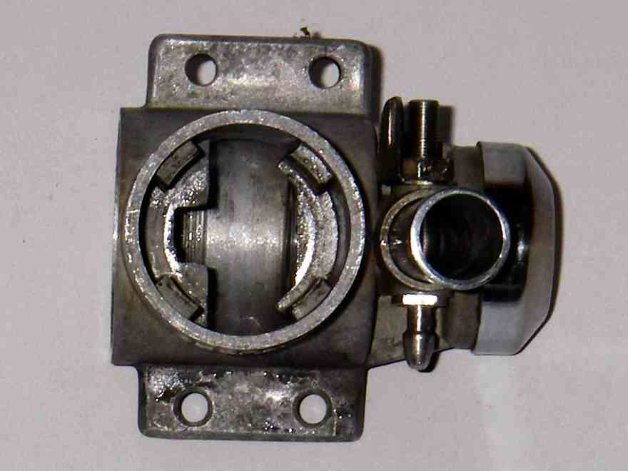
The Strong 19 also departs from Arden practise by eliminating the radial mount in favour of conventional beam mounting. I must confess to a feeling that the beams could have been made a little thicker to help the engine resist crash damage. but on the plus side, they're quite long and the mounting holes are well spaced for stability and stress distribution. The crankcase and main bearing are produced as a single pressure die-casting in aluminium alloy, the case being given a very attractive matter finish seemingly produced by vapour-blasting. All castings are very cleanly executed.
Porting is another area in which the Strong reflects an earlier period. Anyone who has any knowledge of the British-made K Vulture diesels from the late 1940's and the early sandcast Fuji 29 glow models from the same period would recognize one feature of this engine, which is a narrow continuous channel running internally around the complete circumference of the cylinder wall just below the three sawn exhaust ports at the base of the cylinder locating flange. This serves as the actual transfer band providing uninterrupted 360 degree transfer porting.
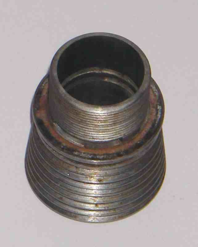
The transfer ports are formed by three sawn slots placed directly beneath the three exhaust ports (the Kemp and Fuji models used internal flute bypass passages to feed the channel). The female threads into which the cylinder screws stop short of the top of the main casting, creating an uninterrupted external 360 degree annular channel around the external cylinder circumference at transfer port height. This channel communicates with the cylinder through the three transfer slots mentioned earlier.
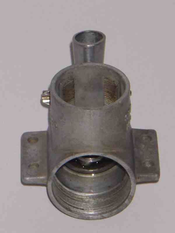
The crankcase transfer passages are formed by four very wide bypass passages which are cast into the main crankcase and interrupt the female cylinder location thread. In effect, the result is an interesting combination of the patented OK Cub transfer system (albeit with four intermediate bypass passages rather than two) and the true 360 radial porting system previously used on the Kemp and Fuji engines. In all cases, a throwback to 1940's technology.
The metal pillars which are left between the three transfer feeder ports and the three exhaust ports directly above are very narrow. Again, I believe that more metal could have been left between the ports for strength reasons. I would advise against tightening down the cylinder of one of these engines too tightly. I'd also have fears about the engine's survival in a hard crash in which the cylinder took a direct impact.
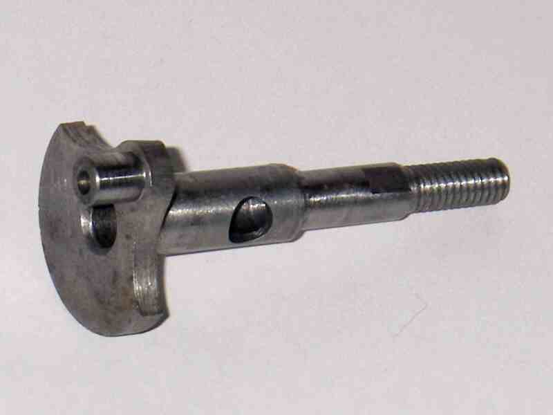
The crankshaft is well finished and nicely counterbalanced, but appears rather skimpy for an engine of this displacement, although it is very well supported by the ball races. The main journal diameter is 8 mm, reducing to 6 mm at the front bearing location. The central gas passage in the shaft has a diameter of 5.2 mm leaving a rather marginal wall thickness of only 1.4 mm. These are all rather "1940's" sizes! The crankpin diameter is 5 mm.
Rather oddly, the induction port itself is a simple 5 mm dia. round hole, which in combination with the round intake venturi gives relatively slow opening and closing of the induction system. By the time in question, oval or rectangular induction ports were generally the order of the day. There is no supplementary sub-piston induction.
The shaft is very carefully fitted to the bearings. It is a smooth sliding push-fit in the bearing centres and spins very freely in the bearings when assembled, with no sign of skidding in the rear race. Fine adjustment of the longitudinal fit is accomplished through the use of a tiny circular bronze shim at the rear of the 6 mm front section. This butts against the rear of the front bearing centre and adjusts the effective shoulder location on the shaft to the bearing spacing. Presumably shims of different thicknesses could be used to eliminate any tendency towards shaft displacement in a crash while ensuring complete freedom from pinching of the bearings when the prop is fitted, but permitting some room for thermal expansion.
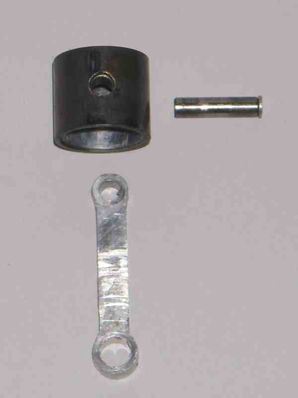
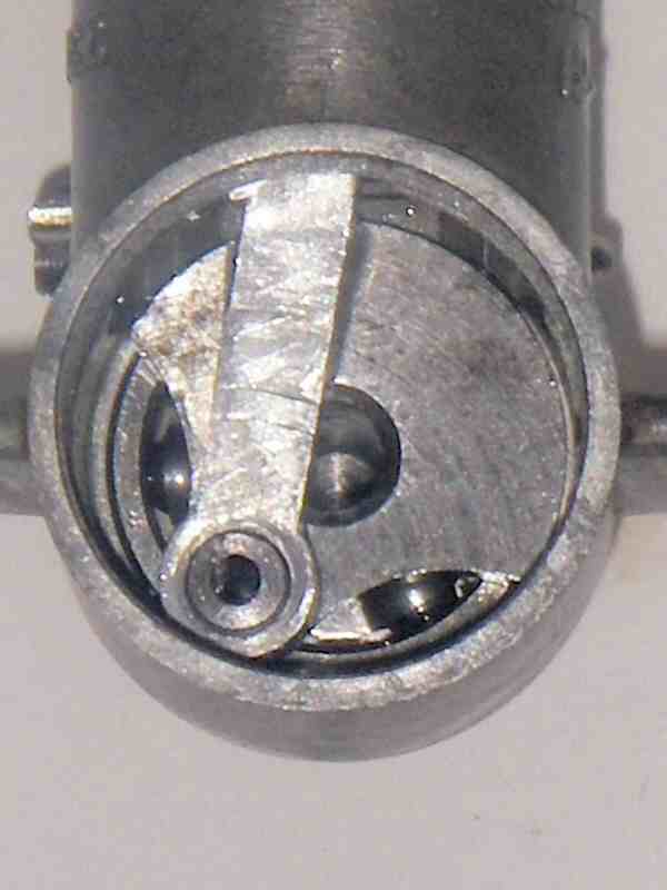
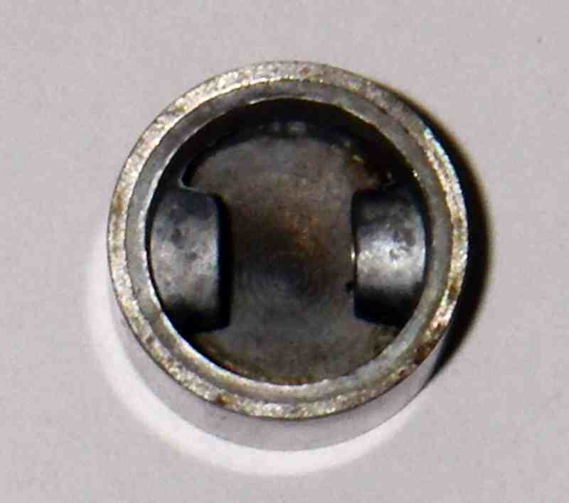
The rod is a simple flat stamping from alloy plate. To make up for this simplicity, the piston is a composite item bearing some structural resemblance to the units employed in the English JB engines as well as the original versions of the AM 35 and ETA 15D diesels. The actual working piston is a thin steel "thimble" with no bosses for the gudgeon pin. This "thimble" fits over a cast aluminium alloy carrier which incorporates very substantial bosses for the 3.5 mm diameter gudgeon pin. However, unlike the English equivalents noted above, the steel "thimble" is drilled through at the front to allow for extraction of the gudgeon pin without removing the carrier. The other end of the gudgeon pin bearing is left blind. The tubular steel gudgeon pin has an aluminium end-pad at the exposed end, the unexposed end being left open. Reference to the sectional view of the engine will show these arrangements very clearly.
Even with the gudgeon pin removed, the internal carrier is immovable in the thimble. The two components must therefore be pressed or shrunk together, and heating the piston during operation will of course only serve to further tighten the fit due to differential expansion of the two materials. As we shall see, this may have been carried too far in the case of the Strong engines.
The composite piston construction was presumably adopted to save reciprocating weight—the resulting piston is substantially lighter than it would be if it was made entirely from steel or cast iron. In fact, the piston, gudgeon pin and con-rod together weigh only 8 gm—very light for a .19 cuin motor of this type.
The system has a significant advantage over the set-ups used in the original AM 35 and ETA 15D in terms of engine maintenance. In both of those cases, replacement of the con rod required the replacement of the entire piston/cylinder set-up—a truly ridiculous arrangement, and one which was quickly discarded by the manufacturers. The Strong design gets around this very neatly while retaining the weight advantage of the composite steel/alloy piston.
The needle valve assembly looks more or less identical to that used in the smaller mid-1960's Fuji models—indeed, it appears possible that the makers of the Strong engine may have obtained their needle valve assemblies from Fuji under contract. This possibility is somewhat heightened by the fact that Haruo Shimizu was an associate of Akira Fujimuro, a well-known Japanese modeller and participant in the model trade who was associated with the Fuji range for some years and who later collaborated with Shimizu-san in the design and manufacture of the Kamikaze 40 twin mentioned earlier.
Contracting-out was a common approach among Japanese manufacturers at the time—indeed, Fuji appear to have been the only Japanese manufacturer who did all of their own manufacturing in-house. Whatever its source, the needle valve assembly is perfectly matched to the engine. The parts list with Alan's engine shows an angled nozzle at the fuel pickup end of the spraybar, but both of our examples feature straight nozzles.
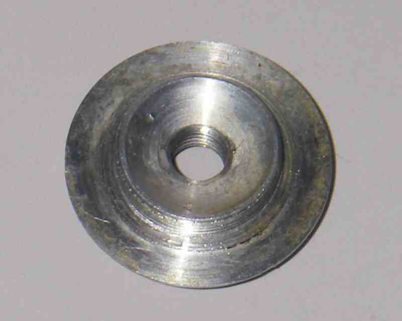
A neat (and once again Arden-like) feature of the Strong is the pressed-on plated brass cover fitted to the front ball race housing. This was presumably included to keep dust and dirt out of the bearing. The prop driver is a die-casting in light alloy and is located on the shaft using a single flat milled into one side of the 6 mm front portion of the shaft, the centre of the prop driver being matched to this single flat. It must be said that prop drivers secured in this way have a tendency to work loose in service and eventually fail altogether by stripping the single key cast into the driver centre. The fit on my example is already a bit "wobbly" despite the fact that the engine appears to have been bench-run only. A taper or splined fitting is far more secure and long-lasting.
The prop is attached using a sleeve nut and washer in the conventional manner. The sleeve nut and washer on my example differ from those seen on Alan's example of the same engine and in the sectional view provided with his example—it's impossible to say if this is a minor variation or a change made to my example by a former owner. Odd if the latter—the engine appears to be almost new and has certainly never been mounted in a model.
One positive consequence of the type of construction adopted for this engine is the fact that it's unusually light and compact for an engine of its displacement, particularly when one considers that it sports a twin ball-race shaft. The illustrated engine weighs in at a very trim 4 5/8 ounces, which is a remarkably low figure for a twin ball race 3.21 cc engine and is substantially less than many 2.5 cc plain bearing models. The plain bearing version of this engine would probably have weighed in at around 4 ounces even! This is comparable to some engines of half the displacement. The measured bore and stroke of this example are exactly 16 mm each, just as stated in the above-mentioned Global Engine Review from 1964.
Another archaic feature of the Strong is a very low compression ratio by mid 1960's standards. This is immediately apparent simply by "feel", and a rough "oil-dropper" measurement of the combustion chamber volume at top dead centre gives a compression ratio of around 6.5 to 1—rather marginal for glow operation. With such a low ratio, one would expect that the use of a fuel with a fair proportion of nitromethane would be obligatory for best results—rather an odd requirement for a sports engine. In addition, a "hot" plug is certainly called for.
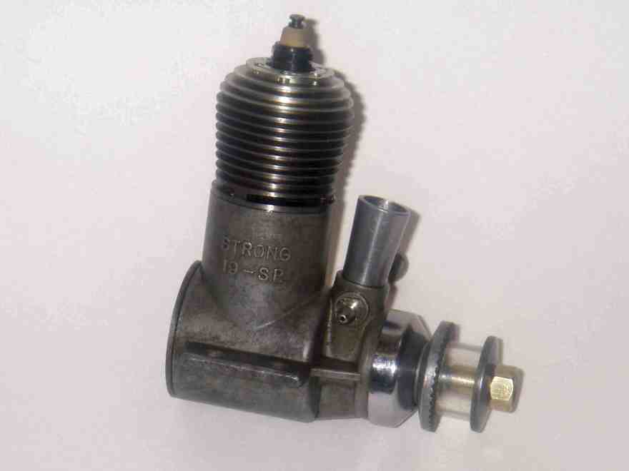
The engine is marked on the right-hand side of the case as "Strong 19—S.P." and on the left side as "3.2 cc". Inquiries to Japanese sources regarding the significance of the letters "S.P." have been somewhat inconclusive—my Japanese informants (including Akira Fujimuro) are unable to suggest any Japanese terms to which these letters could refer. They have put forward the suggestion that it signified "Special", meaning that the BB version of the Strong 19 was seen as the "Special" variant. The fact that these letters evidently appeared only on the ball race version of the Strong 19 does give this suggestion some credibility.
The backplate includes the words "Made in Japan" as well as a reference to a patent which had presumably been taken out by the manufacturers for some aspect of the design. This is presumably a Japanese patent, and it is described on the backplate as "PAT.A.3573 3574".
The manner in which these engines were marked is illuminating. The engine's displacement is given in cc in addition to the cubic inches favoured in the USA and generally adopted by Japanese manufacturers seeking to sell their products in the USA. This seems to suggest that the manufacturers' ambitions were as much concerned with the domestic market as with the export market at the time of their initial entry. The fact that they never appear to have expanded beyond the domestic market, at least in any quantity, suggests that their products were not well received in the marketplace, likely explaining their early and unheralded departure.
A Short-Lived Range
The fact that the Strong engines apparently failed to gain a commercially viable foothold in the domestic market was certainly not down to any limitations in terms of quality. In that sense, the engine fully meets the expectations which had by the time in question become attached to the products of the Japanese model engine industry. My example is very well fitted, and the machining is maintained at an excellent standard throughout. The casting too is extremely clean. Both head and base compression seals are first class, and the shaft spins remarkably freely in its bearings.
It seems likely that the apparent lack of commercial success of the Strong range was due to a failure to promote the engines to the extent required coupled with the undeniably "old-fashioned" design layout which these engines followed in many respects as well as a significant performance deficit by comparison with their contemporaries. Although light, neat and compact as well as being very well made, in technological terms they were a good fifteen years out of date at the time of their introduction. In particular, the ongoing use of radial porting made the fitting of a muffler far more problematic than it was with a side-stack design, and noise was then (as now) becoming a big issue in the modelling world.
When one considers for example that as of 1964 the Strong 19 had to compete domestically with the far more up-to-date Enya 19-IV Model 4004, the excellent 1962 O.S. Max 19 and the updated Fuji 19 side-stack model, it's difficult to feel much surprise at its apparent failure to make any real impression. The one area in which it showed some innovation was the use of a ball-race crankshaft—indeed, it appears to have been the first commercially-produced Japanese .19 cu. in. engine to have done so.
The .09 model of the Strong was similarly disadvantaged—remember, this was a time during which the Cox Tee Dee .09 was ruling the roost in the .099 cu. in. sweepstakes, closely followed in performance terms by the excellent .099 models produced by the Enya company and the ever-improving models being developed by the rival O.S. and Fuji concerns.
As for the twins, the market for them could never have been large at the best of times, and it's no surprise that those rather specialized and doubtless expensive engines failed to make any impression in the marketplace or generate enough revenue to sustain the company. One can only admire the optimistic outlook and genuine enthusiasm which led the manufacturers to enter the marketplace with such spectacularly impracticable products from an introductory standpoint!
So the Strong engines disappeared from the marketplace after what appears to have been a relatively short production run, without having made much of an impression or having left much of a legacy. It seems probable that production lasted little if any beyond the 1964-65 period given by Peter Chinn for the production of the Strong 45 twin.
OK, so now we know a little about the design and construction of the Strong 19. How well did it actually work in practise?! Since we have no published tests to fall back on, we'll have to find out the noisy way.
User Impressions
Since my own example of the Strong 19 BB had clearly been bench-run by a previous owner, I felt that there was little to be lost and much knowledge to be gained by giving my example a little more running on the bench. Not knowing how much previous running the engine had done, I also determined to give it at least a token breaking-in period running rich on an oily fuel, with periodic short lean bursts—the usual running-in procedure for a glow motor with an iron-and-steel piston/cylinder setup.
Accordingly, I set the engine up in the bench with a Taipan 9x4 prop fitted and a 15% nitro content fuel in the tank (in deference to the prevailing low temperatures as well as the low compression ratio) with 25% oil, much of it castor. I reckoned that little harm could be done running the engine carefully on such a combination. I was not expecting any spectacular levels of performance, and my main interest was in seeing how well the engine started and responded to the needle valve.
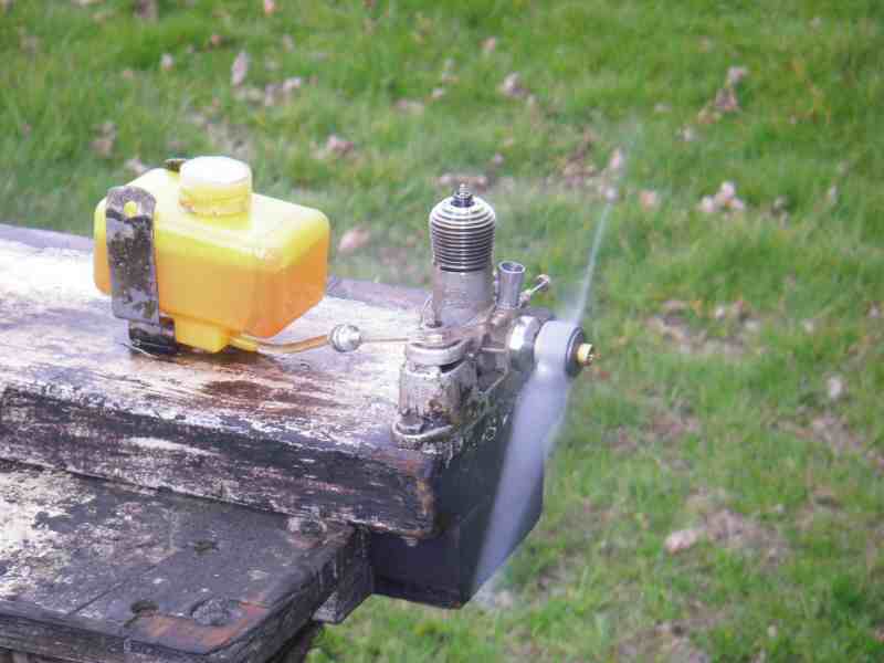
Starting proved to be excellent and completely vice-less provided a decent prime was given. The engine is remarkably docile to handle, due in large part no doubt to the very low compression ratio. However, with a hot plug fitted the plug leads can be removed almost immediately with only a small loss of revs once the engine is running, so the compression ratio is at least adequate on this fuel.
The next thing that one notices is that the engine is extremely LOUD!! Ounce for ounce, this must be one of the noisiest engines ever made! Even the type of noise is aggravating—a sharp-edged crackle that is positively painful! Grab the ear protectors before starting this one!! And fitting a muffler is no easy task given the type of porting used. Here may be another clue to the engine's short production life.
The engine needles well and runs quite smoothly. The problem is that it doesn't run all that fast! I could only get up to 7,700 rpm on the test prop—nowhere at all considering that one of my Enya 19-IV models (dating from the same year of 1964, remember) was easily able to turn this prop at 12,800 rpm on the same day and using the same fuel!
I was very much aware of the fact that the engine didn't seem to be giving its best during this test—there was clear evidence that it was "labouring". The specific problem became evident right after the initial run—as the engine warmed up, the piston became progressively tighter in the upper cylinder. When the engine was stopped immediately after a leaned-out run, the piston could be fairly said to be partially seized in the bore. In my judgment, this must have been costing at least 3,000 rpm—it was that bad.
The engine felt really good when cold, albeit with a trace of stickiness in the upper cylinder typical of a new engine, which this example essentially is. My own view is that the problem rests with the alloy gudgeon pin carrier inside the piston. This is a very tight fit inside the piston "thimble" and undoubtedly expands as the piston warms up, causing the working piston "thimble" to swell.
I got the impression that things were improving a little with running time, but I didn't want to put the required time onto this more-or-less new example. So I ended the tests after some 25 minutes of running, with the tightening-up issue still very much in evidence. I'd guess that at least a further hour would be required to settle the piston into a good high-temperature fit.
However, even after that was done, there's clearly no way that the Strong would get near the performance of the contemporary Enya 19 model tested at the same time. Once again, we see that in performance terms the Strong fell well short of matching its direct contemporaries. More and more, one wonders about the motivation of the manufacturer in producing this interesting but undeniably archaic design.
Conclusion
We hope you've enjoyed this in-depth look as one of the more enigmatic model engine productions of the 1960's. The basis for the engine's failure in the marketplace is clear—it was at least fifteen years behind the times in design terms and fell far short of matching its contemporaries in performance terms. The greatest mystery surrounding this unique production is why it was undertaken in the first place; we leave such speculations to you, the reader!

This page designed to look best when using anything but IE!
Please submit all questions and comments to
[email protected]
|
Unless otherwise expressed, all original text, drawings, and photographs created by
Ronald A Chernich appearing on the Model Engine News web site are licensed under a Creative Commons Attribution-Noncommercial-Share Alike 3.0 License. |

|