Feltham Fliers:
The Rivers Engines
by Adrian Duncan
2012-05
Revised:
2012-10
Part I
-
 Background
 -
 Design Considerations
 -
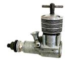
 The Rivers Silver Streak Mk I
 -
 The Rivers Silver Streak Mk I On Test
 -
 Early Competition Success
 -
 The Mk I Rivers Silver Arrow
 -
 The Mk I Silver Arrow On Test
 -
 Upgraded Versions of the Silver Streak and Silver Arrow
 -
 The Mk II Versions of the Rivers Engines
 -
 A Rare Variant—The Rivers Silver Arrow 19
 -
 The Rivers That Never Was—The Silver Bullet
 -
 Further Contest Successes
 -
 A Belated Response—The Silver Streak Mk III
 -
 The End of the Road
 -
 Production Figures
 -
 A Latter-day Clone—The CS Rivers
 -
 Conclusion
Here we take an in-depth look at the Rivers range of model diesel engines from Middlesex, England. These engines were very highly regarded in their day, being built to some of the highest manufacturing standards ever seen in the commercial model engine industry. They were also well out of the rut in design terms, thus meriting our close attention.
When I started this article, I was expecting it to be a relatively straightforward task. After all, we're talking about a company that supposedly made only two versions each of two model diesels—four variants in all, and over a relatively short period of time at that. How much simpler can you get? Accordingly, I began this review as a welcome break from the more complex subjects that I'd tackled for previous issues of Model Engine News.
During the course of my research, I circulated a routine request for information on serial numbers. So much for expectations of an easy ride! I was frankly overwhelmed by the number and range of responses received to this initial request, going far beyond the simple provision of serial numbers to encompass various aspects of the engines' design as well as the issue of model identification. It seems that interest in the Rivers engines runs unusually high, together with a wide range of opinions, many of them contradictory. Sorting out all this material became a genuinely daunting task—indeed, for a while there the data flowed in faster than I could assimilate it! Still, I persevered in the hope that the end result might be viewed as being worth the sweat that it cost!
As a result of the above situation, this article became very much a joint effort as opposed to being my own work. I may have written it all up and assembled the relevant images, but I freely admit that I could not have done so without the very considerable assistance which I received.
Although thanks are due to everyone who helped in the gathering of material for this article, I would particularly like to acknowledge the invaluable assistance of Ian Russell, well-known today for his excellent series of "Rustler" replicas of notable engines from the past. As an active member of the Hayes & District Model Aero Club during the period when the Rivers engines were being developed, Ian was privileged to be among those who participated in the field testing of the Rivers models. In consequence, he became personally acquainted with Bert Rivers and his son Graham (also a Hayes club member) as well as being privy to much of the company's ongoing development work. I'm greatly indebted to Ian for so generously sharing his recollections.
I must also make special mention of David Owen, Jon Fletcher, Maris Dislers, and Brian Cox. All four of these gentlemen went well beyond the limits of my original request for serial numbers, generously sharing their insights into various aspects of the design and production of the Rivers range. I'm most grateful to all four. I also wish to acknowledge the assistance of Bert Streigler, Eric Offen, and Charlie Stone for assisting with the collection of serial numbers and other data. Finally, our Editor, Ron Chernich, gave freely of his time in searching out reference material to which I didn't have access. Thanks to one and all, including those whom I didn't mention by name—you all know who you are!
The initial publication of this article did nothing to slow down the ongoing inflow of information. Ian Russell contacted a number of his former Hayes clubmates to advise them of the article's publication. As a result, additional first-hand information was supplied by such Hayes luminaries as Dave Balch, Robin and Brian Greenaway and Andrew Longhurst—all guys who were "there" during the brief period when Rivers ruled the roost. It was great to have direct contact with individuals who were modeling superstars during my formative years as an aeromodeller!
We were also delighted to receive additional information from readers at large including Jerry Zierdt, who supplied several useful serial numbers.
As a result of all this interest, what had been expected to be a short �n sweet write-up on a relatively straightforward subject turned into my longest and most convoluted article yet. Moreover, the article has had to be significantly updated since its original publication. That being the case, we'd better get right to it! As always, we'll begin with a little background to the Rivers story.
Background
The Rivers engines were developed by the firm of A. E. Rivers, a precision engineering company giving its address as 15 Maswell Park Road in Hounslow, Middlesex. Hounslow is a suburb of Greater London lying on the north bank of the River Thames some miles to the south-west of the City. It is geographically quite close to the successive haunts of the company Electronic Developments Ltd, just across the river at Kingston-on-Thames, West Molesey and Surbiton. Other model engine manufacturers located in the area at various times included Allbon Engineering at nearby Sunbury-on-Thames and International Model Aircraft (FROG) a little to the south-east at Morden. Model engine manufacture was a well-established business in south-west London!
The address on Maswell Park Road lies today in an area which features a mix of residential and commercial properties. The attached image from the �Net shows the building at 15 Maswell Park Road as it was in August 2008, when it was occupied by RGS Gas & Plumbing Services. As of 2012, the property remained in commercial use, being occupied jointly by John Frost Scenery Ltd and Frost's Metals, presumably under the same ownership. It appears from this that the site has remained in continuous industrial use since the time of the Rivers occupancy. However, this location clearly proved inadequate for River's needs as their business expanded, since by August 1960 the company was trading from a new address on Faggs Road in the North Feltham Trading Estate at nearby Feltham, Middlesex. The Faggs Road area remains a centre of industrial activity today.
The introduction of the Rivers engines was very far from being another case of an all-new manufacturer staking his future upon his entry into the highly competitive field of model engine production. The Rivers company was already well established in the precision engineering field prior to its entry into the model engine business. Among other things, Rivers had enjoyed a close sub-contractual relationship with the full-sized aeronautical company Fairey Aviation Ltd of nearby Hayes, Middlesex, having manufactured components for both the Fairey Delta FD.2 supersonic research aircraft (one-time holder of the world air speed record) and the prototype of the revolutionary Fairey Rotodyne VTOL airliner. During the course of these earlier activities, they had already developed and patented the unique cageless needle roller bearing which was to become the defining feature of the Rivers model engine designs.
As of the late 1950's the British Government of the day started sending clear signals that it wished to see a major reorganization of Britain's aircraft industry. This was to lead to Fairey Aviation Ltd first being reorganized as the Fairey Aviation Co Ltd in April of 1959, followed in 1960 by its absorption into the Westland Aviation group. It may well have been the uncertainties created by this developing situation that led to the Rivers company deciding to diversify by branching out into model engine manufacture. Even so, it appears more than likely that the company continued at least at the outset to engage in contract precision engineering work rather than put all of its eggs in the model engine basket.
The development of the Rivers engines appears to have had its genesis in the fact that Graham Rivers, son of company proprietor A. E. "Bert" Rivers, was a keen control-line enthusiast and an active member of the Hayes club, whose home field was at Cranford Park in the vicinity of Heathrow Airport. Although Bert Rivers seems to have been the principal designer of the Rivers engines, there's no doubt that Graham must at least have been instrumental in stimulating Bert's interest in the project. Graham was certainly one of the field testers—prototypes began appearing in his hands at meetings of the Hayes club in the latter part of 1958.
Ian Russell recalls that during the period when the Rivers 2.5cc model (later to be released as the Silver Streak) was under development, Bert Rivers would come out to Cranford Park to watch Graham fly one of the development engines. Bert's announcement to the club members that his goal was to produce a team-race engine to rival the Oliver was greeted with some skepticism—the general consensus was that he was taking on an impossible task which was doomed to failure. The prevailing wisdom was that the Oliver was unbeatable, so why waste time and money trying? Bert's response was that through his attendance at a number of contests he had come to the conclusion that he didn't have to beat the entire field of Olivers—instead, he was really only competing with the top 3 or 4 teams who consistently monopolized the results. In his mind, all the rest were irrelevant!
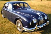
Ian Russell retains some very clear memories of his encounters with Bert Rivers. Among other things, he recalls that Bert drove a Mk1 Jaguar saloon with the narrow back axle, which apparently did nothing for the car's road holding qualities. Bert would sometimes convey one or two of the Hayes club members to various rallies in this vehicle. On one occasion, while belting down a hill into Wycombe on the way to the High Wycombe rally, they could feel the back end hopping around to an alarming degree. This prompted the question "Have you ever noticed a problem with road holding?" "Oh no—never!" said Bert cheerfully, putting his foot down even harder! Clearly a man who met life on his own terms...
Design Considerations
At first glance, the design that was eventually put into production in early 1959, the Rivers Silver Streak Mk I, was a fairly conventional 2.5cc contest diesel of its day. It featured the then-standard mix of FRV induction, reverse-flow scavenging with Oliver-style radial porting and a crankshaft which was carried on a pair of low-friction bearings.
It was the latter feature which really set the Rivers design apart. Most contest diesels of this type used ball races at both ends of the crankshaft. While these were fairly effective both in absorbing radial loadings and end-thrust loadings, they did have the disadvantage that the rear ball race limited the main journal diameter of the shaft. As designers strove for more power through the use of larger internal gas passages and induction ports in the shaft, crankshaft strength became an increasingly serious issue, particularly at the induction port location. Peter Chinn devoted a significant section of his June 1959 "Latest Engine News" column in Model Aircraft to a discussion of this growing problem.
The use of twin ball races inevitably constrained the diameter of the main journal to what would fit through a bearing whose outer race could be accommodated by the crankcase. At the time when the Rivers range first appeared, the greatest diameter yet achieved for a ball-race diesel was 10.5mm (0.413") in the O.S. Max D-15, closely followed by the single rear ball-race Enya 15D at 10.0mm (0.394"). These dimensions were only made possible through the custom production of special bearings. Even so, the relatively large internal gas passages and induction ports used in these designs still left the shaft weaker than ideal—crankshaft failures were not unknown.
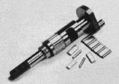
Discussions between Peter Chinn and the Rivers designer confirmed that their crankshaft configuration was a direct response to the issue of crankshaft strength at the induction port location. The Rivers design attacked this problem in a unique way by using a pair of uncaged needle roller bearings, with the rollers operating in direct contact both with their respective crankshaft journals and with the main bearing journal. Each bearing incorporated seven needle rollers which were separated by steel spacers to maintain uniform spacing of the rollers and prevent skewing. The spacers were of course a clearance fit in the bearing so that the load was absorbed entirely by the needle rollers. As noted earlier, Rivers had designed and patented such a bearing prior to becoming involved with model engines.
Since the needle rollers were externally caged only by the internal wall of the main bearing sleeve, they did not have to be slid in an assembled state along the main crankshaft journal as in the case of a ball bearing or caged needle roller bearing but could be assembled in their operating locations prior to installation of the shaft in its bearing. Accordingly, the journal between the two needle roller bearings could be expanded to nominally the same outer diameter as the needle roller bearings when assembled.
The design of the Rivers Silver Streak Mk I took full advantage of this. The shaft featured two lengths of reduced diameter at the bearing locations, into which the needle rollers and their spacers were assembled prior to installation of the shaft. The result was a shaft having needle roller bearings at each end with a plain bearing section in the middle having the same nominal outer diameter as the assembled needle roller bearings. This entire assembly was slid into a hardened steel sleeve which was ground to a constant internal diameter to serve as the main bearing for the composite shaft over its entire length.
The outer diameter of the two needle roller bearing journal lengths in the crankshaft was a respectable 0.350" Although this was a little less than the diameters achieved in some ball race designs, it was not greatly so. More importantly, the fact that these two lengths of shaft were not weakened by the presence of an induction port greatly increased strength at these locations by eliminating the tendency towards the development of stress concentrations which inevitably accompanies the presence of a crankshaft induction port in the main journal.
By contrast, the diameter of the plain bearing length between the needle roller bearings in which the gas induction port was located was a whopping 0.468" (11.88 mm), the largest diameter yet achieved in the design of a 2.5cc FRV contest diesel. This left plenty of metal to allow for adequate strength at this otherwise problematic location. The standard Silver Streak Mk I used an internal gas passage having a diameter of only 0.203", a rather conservative figure which resulted in a wall thickness of 0.074" at the roller bearing locations. The works-tuned version of the engine had an enlarged internal gas passage diameter of 0.240" which was still easily accommodated, although wall thickness at the rear roller bearing journal was reduced to a rather more marginal 0.055" albeit without the strength-sapping presence of an induction port.
Of greater significance in a performance context was the fact that the unusually large journal diameter at the induction port gave rise to a very high annular surface speed at a given rate of rotation. This in turn significantly reduced the time taken up by the opening and closing of the induction port, allowing for very precise timing. Moreover, the annular length of the crankshaft induction port was necessarily greater for a given opening period, being formed by cross-milling. All of this promoted a longer fully-open dwell period for the induction system—a great benefit to higher performance.
A final advantage of the needle roller bearing arrangement was the fact that the radial loads on the shaft were resisted by a significantly greater proportion of the crankshaft journal length. This too might be expected to promote greater durability of the shaft and bearing.
However, there were a number of definite downsides to this design. First and foremost, it was clearly very expensive to manufacture. Makers of ball-race diesels could simply buy their bearings in job lots from specialist bearing manufacturers. Not so with the Rivers—the needle roller bearings for each engine had to be individually manufactured and fitted to extremely fine tolerances. The manufacturers stated that the rollers themselves were ground 1.5 mm (0.0591") diameter items which were mated to nominally 0.350" dia. journals which were themselves ground to limits of minus two tenths of a thousandth of an inch (0.0002" or 0.0051mm). This resulted in an external diameter of the assembled bearing of 0.04682" with a minus 0.0002" tolerance. The internal diameter of the steel main bearing sleeve was ground to 0.4684", giving the needle roller bearings a running clearance of 0.0002", at a tolerance of minus "two tenths", which was apparently considered ideal.
At the induction port location, the crankshaft journal was ground to 0.4682 minus 0.0004"—0.0006", thus ensuring that the assembled rollers stood proud of the central plain bearing journal section by some 0.0002" It will be seen from all of this that the manufacture of the Rivers engines involved precision grinding of a very high order indeed as well as extremely close attention to manufacturing tolerances. Not a challenge that many commercial model engine manufacturers hoping to make a profit would care to take up!
This was not the only manufacturing challenge. The fact that the crankshaft had to serve as the inner race of a needle roller bearing meant that its surface hardness was critical. Any errors in getting this right would likely result in spalling of the hardened skin of the bearing surface. The design therefore called for a very precise heat treatment specification. The shafts were machined from 85 ton tensile alloy steel which was then hardened on the journal surfaces to Rockwell 60. Following this stage, the crankpin and prop mounting shaft were both tempered. Any error in the implementation of this exacting heat treatment sequence could have highly negative consequences.
A further issue was the fact that, generally speaking, friction losses in needle roller bearings in applications of this sort tend to be substantially higher than with good-quality ball races. This is in large part because of increased viscous drag arising from the presence of lubricant. The needle rollers have to overcome the drag exerted by an oil film extending the full length of the bearing—a far greater area than that for a ball bearing with its spot contact as opposed to the line contact of the needle rollers. The spacers used in the Rivers design would have made a significant further contribution to this problem.
In this regard, there is a persuasive school of thought which considers needle roller bearings to be quite unsuitable for high-speed applications of this kind. The famous Schaeffler Group of INA bearing fame state categorically that needle roller bearings are unsuitable for high rotational speeds or high radial loadings. They also note that lubrication requirements for such bearings are critical, with over-lubrication actually being a particular issue. This condition is very likely to occur in a model engine application. It's possible that the use of spacers in the Rivers bearings may have allowed the successful use of the bearings at higher speeds, but the other problems would no doubt remain.
Furthermore, while the Rivers needle roller bearings doubtless did a good job of absorbing the radial loadings to which the crankshaft was subjected, they did absolutely nothing to assist with the thrust loadings generated during operation. In that respect, the engines were no better than a plain bearing model. In fact, based on the earlier discussion, it's actually likely that the Rivers shaft design was little better than a good-quality plain bearing at higher speeds, although the engines certainly felt extremely "free" when turned over by hand at rest. While not themselves ideal in this application, ball-races almost certainly do a better job overall.
I am one of those who believe that the optimum set-up would have been a quality ball-race at the rear and the Rivers needle roller bearing at the front, provided this could be accomplished without significantly reducing the journal diameter at the induction port. This would have dealt far better with axial loadings while providing outstanding radial support to the prop driver assembly at a location in which radial loadings should be relatively low. As we shall see later, there is evidence to suggest that Rivers themselves eventually came round to this point of view.
The final downside of the use of the type of bearing employed was the indisputable fact that cleanliness was absolutely paramount if the roller bearings were to be maintained in good condition. Given the clearances involved, it's obvious that the intrusion of even the smallest particulates could result in skidding and/or scoring of the needle rollers. It might accordingly be expected that use of these engines in environments in which dirt ingestion was a potential issue would be highly inimical towards long life.
The Rivers Silver Streak Mk I
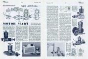
As far as I'm aware, the introductory announcement of the Rivers Silver Streak appeared in the "Motor Mart" feature of the March 1959 issue of Aeromodeller magazine. This was accompanied by the appearance of full-page advertisements in the major British aeromodelling magazines. These initial advertisements cited the manufacturer's previous experience in the aviation industry and went on to extol the virtues of the unique roller bearing crankshaft design. The stated selling price of the engine was a healthy �6 10s 0d (�6.50 in modern money)—a very high figure for an over-the-counter 2.5cc diesel in the context of the contemporary British market. Trade inquiries were invited—seemingly the company was still in the process of establishing its distribution network at this time.
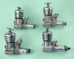
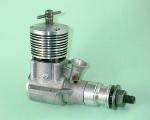
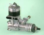
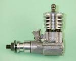
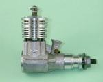
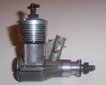
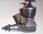
In terms of the engine's construction, we have already covered the crankshaft configuration in great detail. The rest of the engine followed basically conventional lines for a 2.5cc FRV contest diesel of its day. It featured reverse-flow scavenging with radial Oliver-style porting, a one-piece crankcase casting, a cast-iron piston and contra-piston operating in a steel liner, a separate bolt-on aluminium alloy cooling jacket and a screw-in backplate.
Bore and stroke of the Rivers Silver Streak were identical at 0.5782" (14.686mm) apiece for a displacement of 2.49cc. The engine weighed in at a relatively healthy 5.85 ounces (166 gm), a fair proportion of which was in the crankshaft/main bearing assembly. This was another disadvantage of the bearing design—it made higher-than-average weight inevitable. Although not excessive by today's standards, this was a pretty substantial weight for a 2.5cc diesel at the time.
The hardened and ground steel cylinder featured four sawn exhaust ports uniformly spaced around the cylinder port belt which also served to locate the cylinder vertically on the top of the crankcase. Four transfer ports were drilled at an upward angle from below the port belt, emerging in the pillars between the exhaust ports and overlapping the exhaust ports to a significant degree. These transfer ports were fed by downwardly-expanding bypass passages of triangular form, one to each port, which were milled into the outer wall of the lower cylinder liner.
The piston and contra-piston were both machined from high-grade Meehanite cast iron. Somewhat unusually, the contra-piston featured three annular grooves around its external circumference into which was packed molybdenum disulphide grease prior to assembly. This was presumably intended to promote smooth operation of the compression control, particularly during the break-in process. The con-rod was machined from DTD 363 alloy. A praiseworthy feature was the very generous small end length incorporated in the rod. In conjunction with a lightly press-fitted gudgeon pin, this might be expected to give excellent con-rod life.
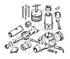
The aluminium alloy backplate was of the conventional screw-in variety. In order to provide clearance for its installation, the base of the cylinder liner was partially machined away beneath the rear exhaust port. This had the benefit of ensuring that if the engine was ever dismantled, it could only be re-assembled with the cylinder in the same orientation as before. Somewhat confusingly, the exploded view provided with the instruction leaflet showed the relieving section of the lower liner placed at the front rather than the rear—a potential trap for those not familiar with model engine assembly!
Another potential trap for the unwary was the fact that the cylinder retaining screws were located asymmetrically rather than equally spaced around a pitch circle in the conventional manner. The cooling jacket could thus be installed in only one of two potential orientations rather than the usual four.
The design progression of the prop mounting system clearly demonstrated the manufacturers' early awareness of the need to prevent the ingress of foreign material into the engine's main bearing assembly. The very earliest Silver Streaks used a conventional prop driver which simply butted up against the front of the main bearing with a small operating clearance. This of course left the front needle roller bearing exposed to the ingress of dirt as a result of crashes or operation in dusty conditions.
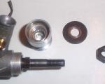
The manufacturers clearly became aware of this issue very early on, since a change was quickly made to a prop driver of the wrap-around type. This incorporated a recess at the rear which enclosed a 1/4" long section of the main bearing at the front. This section of the bearing was machined down to an external diameter of 0.625" to accommodate the driver. There was thus little chance of dirt entering the main bearing at the front—any foreign material which might get into the hollow section of the prop driver from the rear would be centrifugally purged by the escape of oil through the front bearing during operation. The prop was secured to this assembly using a choice of ether a conventional nut and washer or a turned aluminium alloy spinner nut, both of which engaged with an externally-threaded extension of the crankshaft in the conventional manner.
The engine was completed by a needle valve assembly of more or less conventional form. A brass spraybar was used in conjunction with an aluminium alloy thimble which was tensioned with a coil spring. Appropriately enough given the engine's primary intended application for control line service, the needle was angled back to the left (facing forward in the direction of flight), thus facilitating sidewinder mounting and also placing the needle very conveniently when the engine was mounted in an inverted orientation, as it generally would be in a team racer.
Most (but not all) of the Rivers engines bore serial numbers, generally (but not invariably) stamped on the outer edge face of the left-hand mounting lug (facing forward in the direction of flight). Indications are that the numerical sequence for the Silver Streak started at engine number 1 and continued uninterrupted through the changes that produced the Mk II model (see below). An A prefix appeared in conjunction with the engine's serial number.
On the very earliest examples, it appears that the mounting lugs were not machined in any way. In addition, we noted previously that these early engines lacked the wrap-around prop driver of the later models. We are aware of engine numbers A65 and A127 of this type. For convenience when discussing such issues as production figures (see below), I will henceforth refer to this as the Rivers Silver Streak Mk Ia. It's clear from the known serial numbers that this must be considered to be by far the rarest Silver Streak variant.
Later examples had the undersides of their mounting lugs machined flat to provide a more secure mounting. The outer edges of the lugs were also machined. In addition, the wrap-around prop driver was added. We see these changes by the time we reach previously-illustrated engine number A146. For clarity during later discussions, it seems appropriate to refer to this variant as the Rivers Silver Streak Mk Ib.
From the outset, the Silver Streak was also made available in a "works tuned" version, albeit at a premium price of �8 17s 2d (�8.86 nowadays). This unit featured a certain amount of hand-finishing of the induction and transfer porting along with an enlarged 0.240" dia. central gas passage in the main shaft. The enlarged gas passage had to be created during the original manufacturing process prior to heat treatment and fitting of the needle roller bearings, which meant that the tuned version of the engine was in fact a distinct production—the company specifically noted that they could not accept standard engines for after-sale tuning and that tuned engines had to be ordered as complete new units direct from the factory.
The resulting unit was substantially faster than the standard motor, at the possible cost of a degree of increased fragility. The letter T was added as an extra prefix to the serial number to identify these tuned models. Engine number TA735 is a reported example of this type. We are also aware of engine number A325T, showing that the letter T sometimes appeared as a suffix on the tuned examples.
The standard needle roller bearing assembly used in these engines was in fact a simplified version of a previously-developed patented Rivers needle roller bearing design in which a combination of balls and needle rollers was employed. The more complex bearing used a larger number of rollers which were separated by rows of balls rather than by steel spacers. A single spacer was retained, mainly to prevent skewing of the rollers. The balls were a clearance fit in the bearing, the result being that the applied load continued to be carried entirely by the rollers. The advantage of this design was reduced viscous drag and friction within the bearing during operation, although assembly in a model engine must have been a nightmare. Regardless, bearings of this type had reportedly been used successfully in a number of the prototype engines and could be supplied to order with the tuned version of the Silver Streak, albeit at a further additional cost.
As one might expect from the earlier comments regarding the engine's design and construction, workmanship throughout was of an extremely high order. Indeed, it had to be given the nature of the design. The question now was—how effectively did all of this care and effort translate into performance? The model engine testers of the day were all ready to answer that question.
The Rivers Silver Streak Mk I On Test
The first published test of the Rivers Silver Streak Mk I appeared in the April 1959 issue of Aeromodeller magazine, the tester being Ron Warring. Allowing for editorial lead-time, this implies that Warring had been unusually quick to get his hands on the test engine. The Silver Streak had of course been featured in the previous month's "Motor Mart" column, but even so this was a remarkably quick reaction to the engine's appearance.
The variant tested by Warring was a Mk Ib variant featuring the wrap-around prop driver, proving that it was in fact a refined production model with a serial number above A127 as opposed to a prototype or an early production unit. This implies that the company had been very quick indeed to make the changes which resulted in the Mk Ib variant, quite possibly during the pre-release stock build-up which routinely preceded the announcement of any new model for which brisk sales were anticipated.
Warring was generally extremely complimentary regarding the engine. He praised the standard of workmanship to the skies, characterizing it as "of the highest order and generally better than that found on normal production engines". In fact, he went so far as to state outright that the Silver Streak was "manufactured to some of the highest standards we have come across in the modelling world". He commented at length on the very close limits to which the engine was constructed, noting that this gave rise to a need for a longer-than-usual running-in period. The manufacturers stated that a running time of some 5-6 hours was generally necessary for maximum performance to be achieved, a recommendation which Warring endorsed.
In terms of the engine's performance, Warring characterized its handling and running characteristics as "extremely good". He noted a certain preference for a fairly heavily nitrated fuel, suggesting a minimum nitrate content of 3%, but found that starting was excellent either on a prime or a finger-choke. Control response was found to be essentially non-critical, with hot restarting being immediate without any adjustment of the settings. This boded well for the engine's effectiveness in the team race application for which it was primarily intended.
Warring extracted a peak power output of 0.277 BHP @ 15,800 rpm. This was the first indication of a potentially problematic future for the engine—a number of competing 2.5cc diesels from Britain and elsewhere had previously been tested and found to equal or exceed this level of performance, some by a significant margin. Although Warring did not say so, it appeared on the basis of this test that all of the meticulous work involved in designing and constructing this engine to such high standards had not translated into anything special in the way of performance apart from the unusually high peaking speed for a diesel. For an engine with such a high selling price even in standard form, this was not a positive finding.
Warring summarized his report by once more praising the standard of workmanship embodied in the Silver Streak. He justified the engine's higher-than-average selling price on the basis of workmanship rather than performance, although he did note that there was undoubtedly sufficient performance in the design to make the engine a potential contest winner. Finally, he noted that a 3.5cc version of the engine (soon to appear as the Silver Arrow, of which more below) was even then under development.
Unaccountably, Model Aircraft tester Peter Chinn was quite a bit slower off the mark in getting to grips with the Silver Streak. Chinn first noted the appearance of the engine in passing as a footnote to his "Latest Engine News" column in the May 1959 issue of Model Aircraft, going on to discuss the engine in more detail in his June 1959 column in the same magazine. However, it was not until the November 1959 issue of the magazine that his test of the engine finally appeared.
Chinn began by reminding his readers of his earlier discussion regarding the growing issue of crankshaft weakness with high-performance 2.5cc FRV diesels, going on to detail the manner in which this issue was addressed in the Rivers needle roller bearing design. Like Warring before him, he praised both the quality of the engine's construction and its handling attributes, characterizing the latter as being "of a very high order". He found starting extremely easy following a few choked turns and praised the non-critical nature of the controls. He described running qualities as "excellent in all respects".
However, all was not perfect. Reading between the lines, one gets a sense that, like Warring before him, Chinn was a little disappointed by the performance achieved despite such a high level of design and manufacturing effort. One gets the feeling that the power output achieved by the Silver Streak fell somewhat below Chinn's expectations. Maximum torque was found at 9,000 rpm, the corresponding Brake Mean Effective Pressure being only around 56 psi, considerably lower than that achieved with several competing models from other makers. By way of compensation, torque was well sustained at higher speeds, the result being that the engine was found to develop a maximum output of 0.283 BHP @ 16,000 rpm—an unusually high peaking speed for a diesel of this layout.
The results of the above two tests were remarkably consistent. They both made it clear that the Silver Streak was very much a high-speed engine which should be propped for around 15,000—16,000 rpm in the air to get the best out of it. However, they also revealed the underlying weakness of the Silver Streak's position in the model engine market as it then existed—in standard form, it was undeniably down on power compared to other competing models despite its higher-than-average price. The tuned engine would doubtless do better, but the even greater cost of that model was a significant deterrent.
Early Competition Success
Based upon the contemporary contest reports, it would appear that more or less the entire membership of Graham Rivers' Hayes cub quickly equipped themselves with Silver Streak motors! At this time, the Hayes club numbered some of Britain's most accomplished competitors among its members, and these individuals were keen to demonstrate the potential of the new engine. In effect, the members of the Hayes club became the Rivers "works team"! Ian Russell was among the members of this elite group, which also included team-race expert, Dave Balch, and combat ace, Robin Greenaway.
By August of 1959 members of the Hayes club had posted a highly respectable 95 mph average speed in testing for a Class A team race event. Hayes club member Dave Balch was prominent in leading this effort, acting as pit man for models powered by his own tuned engines supplied by the factory. Tuned examples of the engine managed to reach both semi-finals in Class A team racing at the 1959 Godalming rally. In a team racing context, the engine was showing early promise, although it had yet to win a major event.
However it didn't stop there—the engine quickly found its way into combat circles as well. Robin Greenaway was a leading light in this category of competition, in which things quickly began to look very promising indeed! At the Dartford rally on June 7th, 1959, the tuned Silver Streak notched up its first major win, finishing on top of the combat heap. Equally impressively, Silver Streaks powered four of the 8 combat quarter-finalists at the 1959 Northern Heights gala, with a tuned example reaching the finals. A tuned Silver Streak also made it into the combat finals at the 1959 Ashford rally, competing against a prototype Silver Arrow 3.5cc model (of which more below).
However, the Silver Streak continued for the most part to fall slightly short of matching the performance of the Oliver Tiger, which remained the standard against which all others were judged. It was clear that further work would be required in order to place the Silver Streak in a truly competitive position in the British marketplace. Having established his goal of beating the Olivers at their own game, Bert Rivers wasn't about to give up now!
Meanwhile, back at the factory... During the summer of 1959 a number of experimental models had been constructed and tested. One of the more interesting of these prototypes was a 3cc diesel which was in effect an overbored Silver Streak Mk I featuring a revised cylinder liner having Cox-style fore-and-aft transfer porting with twin opposed exhausts and a modified crankcase incorporating twin bypass passages at front and rear to match the transfers.
Ian Russell tells us that these engines were very good performers indeed. They were apparently made primarily to give the combat crowd an edge while the 3.5cc Silver Arrow was still in its development stage. Four examples of the 3cc model were given to Hayes club members, of whom Ian was fortunate enough to be one. Ian believes that more than four of these units were made, but has no knowledge of where the others went. He ended up using his example of the 3cc model to power his first-ever Gold Trophy control-line stunt entry at the 1959 British Nationals, in which he finished a very creditable 7th. He still has the engine today (2012). Interestingly enough, it bears no serial number.
The appearance of the 3cc model at the Nationals was noted in the July 1959 Aeromodeller report on that event. A glow-plug version of this design was also tested to serve as a possible basis for a .19 cuin glow-plug model with which to challenge the American market. However, the 3cc model never materialized in production form, either in diesel or glow-plug configuration. Pity ...
There were also four sand-cast prototypes of a 3.5cc diesel which used the same crankshaft as the Silver Streak albeit with a greater throw. Peter Chinn conducted private tests on one of these for the manufacturers, being quite impressed according to his report in the "Latest Engine News" feature of the October 1959 issue of Model Aircraft. Preliminary tests by Aeromodeller staff on another prototype yielded a peak output of 0.35 BHP@15,000 rpm, although the manufacturers reportedly expected the production version to beat these figures. Another of these prototypes made it into the combat finals at the 1959 Ashford rally, as mentioned earlier.
The "Motor Mart" feature in the November 1959 issue of Aeromodeller made reference to all of these experiments, noting that the only one which was set to appear in commercial form was the 3.5cc diesel model, to be called the Silver Arrow. It's now time to take a closer look at this engine.
The Mk I Rivers Silver Arrow
As noted earlier, the planned advent of a 3.5cc version of the Silver Streak had been noted by Ron Warring in his April 1959 test of the Mk I Silver Streak. The first notification direct from the manufacturer appeared in the company's July 1959 advertisements. These focused on the Silver Streak which was then in full-scale production, but did include a statement to the effect that a 3.5cc version of the engine would be available "shortly".
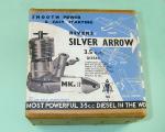
The Mk I version of the 3.5cc Rivers Silver Arrow finally made its appearance in company advertisements in September 1959. The advertised selling price was �6 5s 8d (�6.28), slightly less than the introductory price of the Silver Streak. The price of the latter model was immediately reduced to �6 5s 8d to match. The tuned version of the Silver Streak continued to be offered at a reduced price of �7 15s 0d.
Despite the engine's appearance in the advertisements, it seems that the production models did not actually begin to reach the marketplace until late November 1959. Peter Chinn noted this fact in his December 1959 "Latest Engine News" column in Model Aircraft (clearly written in mid November to meet editorial deadlines), citing production problems with the gravity die-cast Silver Arrow crankcases as the reason for the delay.
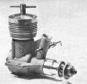
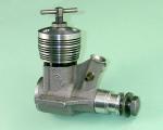
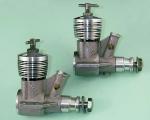
Superficially, the new model appeared to be an enlarged version of the Silver Streak, being built to a basically similar design specification. However, unlike some other enlarged versions of smaller engines, the Silver Arrow was not merely a bored-out Silver Streak but was an all-new production throughout—everything was enlarged, the only interchangeable components between the two models being the needle valve and prop mounting assemblies. The new model featured square bore and stroke dimensions of 0.647" (16.433 mm) apiece for a displacement of 3.487cc. Weight of the engine was a healthy 7.1 ounces (202 gm).
The most significant departure from the design of the Silver Streak was the Silver Arrow's use of only three exhaust ports instead of the four used in the smaller model. These were accompanied by three upwardly-angled transfer ports between the exhaust openings. The transfer ports overlapped the exhaust to a greater degree than in the case of the Silver Streak, giving a relatively long transfer duration with a minimal blowdown period.
The crankshaft design followed that of the smaller engine, the same uncaged needle roller bearing system being employed. According to Peter Chinn's description in his February 1960 test of this model (see below), the shaft was essentially the same as that used in the Silver Streak apart from the increased throw. Chinn also noted that the internal gas passage and induction port were both enlarged to accommodate the larger engine's increased appetite for fuel mixture. This may have led to reliability problems, as we shall see. The engine featured the same externally-threaded extension at the front of the shaft for prop mounting purposes. As with the Silver Streak, buyers could order the engine with either a conventional prop nut or a neat aluminium alloy spinner nut.
The induction period was actually increased over that used in the Silver Streak, the intake opening at 35° ABDC and closing at 45° ATDC for an unusually long induction period (for an FRV engine) of 190°. This was supplemented by a period of sub-piston induction. Exhaust timing was equally aggressive, with an opening period of 165°. This is the explanation of the very "powerful" sound of one of these engines in operation!
Other departures from the earlier design included the use of an unusually long integrally-cast venturi which was cross-drilled at 90° to the engine's axis for the spraybar. This meant that the spraybar could be assembled on either side of the engine with equal accessibility. The screw-in backplate too was modified from the earlier design. It now featured an internally-threaded central boss which was normally sealed with a screw-in brass plug. However, Rivers could supply either a nipple for crankcase pressure feed or a crankcase bleed lever fitting through which a measure of speed control could be obtained.
Like their Silver Streak siblings, the Silver Arrows were numbered sequentially on the left-hand mounting lug, starting at engine number 1. In this case, though, the letter prefix B was used to indicate that this was a 3.5cc model. We are aware of engine numbers B38, B101, and B120. as well as engine number B205 which was reported by Brian Cox following the initial publication of this article. As before, tuned engines were available from the manufacturers, although in the case of the Silver Arrow the letter T usually appeared as a suffix to the main number rather than as a prefix. Engine number B2132T exemplifies this system. There have also been persistent reports of Silver Arrows which feature no serial number at all. We'll comment further on this latter point in a subsequent section.
The original version of the Silver Arrow just described is by far the rarest variant. Perhaps this reflects the fact that many of them are known to have broken their crankshafts. Peter Chinn made specific reference to this problem in his April 1960 "Latest Engine News" column, noting that a larger shaft of different design was then in the process of being introduced for both the Silver Arrow and Silver Streak. Although this can't be proved, it's likely that any engines returned with broken shafts under guarantee from March 1960 onwards were fitted with the larger shaft, necessitating a replacement case to accommodate the larger-diameter main bearing sleeve. Logical move—why fit a replacement for a busted shaft that you suspect may simply break again? This may well explain the reported existence of a number of Silver Arrows with no serial numbers—they may be upgraded early models.
As a high-performance diesel of 3.5cc displacement, the Silver Arrow's obvious application was in control line combat, since the then-current SMAE rules allowed engines of up to 3.5cc in that category. We've noted previously that even before its release to the public it had attracted some attention in that category in prototype form. This being the case, test reports on the performance of the production version were awaited with some interest.
The Mk I Silver Arrow On Test
This time, Peter Chinn was first into the field with a published test of the production version of the Silver Arrow. His report appeared in the February 1960 issue of Model Aircraft. It is perhaps a measure of the extent to which Chinn was impressed by this engine that he began his report with what amounted to a defence of his findings in light of the known fact that different examples of the same engine can undeniably perform at different levels. He posed the question regarding whether or not all production examples would come up to the standard displayed by his test engine, concluding that regardless of the answer, the Silver Arrow was "inherently, an exceptional engine, with handling and performance characteristics that lift it well above the general run of "large" diesels".
Chinn stated without prevarication that his test engine's power output "far surpassed that of any other 3.5cc diesel produced to date". He characterized the engine's handling qualities as "remarkable", stating that it was "quite the easiest starting 3.5cc diesel we have encountered in recent years".
The output recorded by Chinn was 0.395 BHP @ 15,800 rpm, both figures being unusually high for a diesel of this displacement. Chinn commented on the obvious fact that despite its relatively large displacement for a diesel, the Silver Arrow was (like its smaller Silver Streak relative) essentially a high-speed engine. He also noted the engine's preference for a heavily-nitrated fuel, exactly like its smaller brother.
Chinn concluded his report by noting that while the Silver Arrow was relatively costly at �6 5s 8d, this could hardly be considered unreasonably expensive considering the engine's "all-round excellence". High praise indeed from Britain's most respected model engine expert!
In the case of the Silver Arrow, Ron Warring of Aeromodeller magazine lagged as far behind as he had been ahead when testing the Silver Streak. His test report on the Silver Arrow did not appear until the July 1960 issue of the magazine. When it did so, it was every bit as complimentary as Chinn's had been. He confirmed that the engine was "remarkably easy to handle" and praised its running characteristics in addition. He also commented on the outstanding quality of the engine's construction.
Warring agreed with Chinn that the Silver Arrow was definitely a high speed engine. He measured a peak output of 0.38 BHP @ 15,500 rpm, both figures being slightly lower than those reported by Chinn. This was a normal occurrence—for reasons which are unclear but which must relate to engine testing and management techniques, Chinn generally tended to find more power at higher speeds than Warring in tests on the same engine.
One accessory tested by Warring which had escaped Chinn's attention was the air-bleed throttle which could be installed in the central backplate spigot in place of the standard brass plug. Warring found that this gave quite reasonable throttle control, a speed reduction of around 50% being recorded with the air bleed fully open. Response to closing the air bleed was found to be immediate, the engine returning instantly to full speed.
Warring's summary was as complimentary as Chinn's had been. He stated that the engine appeared to be "out on its own as regards 3.5cc diesel performance". He characterized the Silver Arrow as "a first class engine in every respect", noting particular that until another manufacturer challenged it with a new product, it should be "about the top engine for combat" (at this time, the SMAE combat rules still allowed engines of up to 3.5cc displacement).
Warring noted the fact reported earlier by Chinn that problems had been experienced with some of the earlier engines with crankshaft breakages. Although according to the manufacturers this problem had been confined to a specific batch of crankshafts which had been made too hard, Warring confirmed that the company had elected to play safe by increasing the roller bearing journal diameter of the shaft in both the Silver Streak and Silver Arrow from 0.350" to 0.406" This necessitated an increase in the number of rollers used from seven to eight to maintain an appropriate spacing. The diameter of the central section of the shaft was of course increased to match.
The prop mounting system had also been changed from a threaded extension of the shaft to a threaded recess in the shaft interior at the front into which a steel 0 BA prop mounting bolt (or alloy spinner bolt) was screwed. A hard impact might be expected to bend or break the bolt rather than damage the shaft—a far less costly repair, especially given the complexity of the Rivers crankshaft assembly!
This change actually appears to have preceded the increase in the diameter of the main journal, since although the example tested by Warring featured the newly-introduced internally-threaded shaft with prop bolt, it retained the earlier 7-roller bearings (clearly seen in the component images which accompanied the test report). In addition, it retained the air-bleed spigot in the backplate which was about to be dropped and also lacked the steel hex nut compression lock which was applied to the revised models. It was thus identical to the example tested by Peter Chinn apart from the method of prop mounting.
In commenting on the above changes in the shaft design, Warring was in fact speaking about the updated versions of the two models which were just being released at the time when his test report on the Mk I version of the Silver Arrow was written. Let's have a look at those models.
Upgraded Versions of the Silver Streak and Silver Arrow
Peter Chinn's "Latest Engine News" article in the June 1960 issue of Model Aircraft included the announcement that the previously-reported revisions to both the Silver Streak and Silver Arrow were then being implemented, with the Silver Arrow being the first of the two models to appear in upgraded form. Emphasis was placed both upon the increase in shaft journal diameter and the change from an externally-threaded front extension for the prop to an internally-threaded shaft with prop bolt. The initial advertisement for the upgraded models appeared in the July 1960 issue of Aeromodeller. Both models were offered at an unchanged price of �6 5s 8d (�6.28).
At this point, it's unfortunately necessary to interrupt our story to deal with a somewhat controversial matter—the question of model identification as applied to the Silver Arrow. There is general agreement that the revised shaft is the defining feature of what was called from the outset the Silver Streak Mk II, being referred to as such by the manufacturers in their advertising. However, this matter is far less clear in the case of the Silver Arrow. Let's review the issue in detail.
It seems best to begin by recording the three distinct production variants of the Silver Arrow of which we are presently aware:
- Early model as tested by Peter Chinn and referred to by him in his April and July 1960 articles, with the smaller-size 7-roller shaft and externally threaded extension for the prop nut or spinner nut. �The serial number range clearly started at B1, but to date the only reported engine numbers for this type are B38, B101, B120, and B205—scarcely a statistically reliable sample! We therefore have no firm estimate for the upper limit of the range, except to say that by engine number B315 it had been supplanted by the next model in the series (see below). The implication is that no more than some 300 examples of the Mk. I Silver Arrow were manufactured—quite possibly less.
- Significantly revised model heralded in April 1960 and further detailed in July 1960 (by Peter Chinn in both cases) with larger 8-roller shaft and prop-bolt (or spinner-bolt) with internally threaded shaft, also missing the former spigot in the backplate for the air-bleed accessory. A steel hex nut was now included to serve as a compression lock. Presently-known serial number range—B315 to B1201. It�s noteworthy that there is a seemingly anomalous gap in the sequence between engine number B315 and the next highest reported number B635. We�ll have more to say about the implications of this gap as we proceed.
- Further slightly revised model which was identical in all respects to the previously-described variant apart from the addition of a pressure tapping point cast onto the underside of the main bearing as in the Mk II Silver Streak.�Presently-known serial number range—B315 to B3114. It�s noteworthy that there is a seemingly anomalous gap in the sequence between engine number B315 and the next highest reported number B635. We�ll have more to say about the implications of this gap as we proceed.
For the sake of clarity during the following discussion, we will refer to these variants as Type 1, Type 2, and Type 3. Readers should remain mindful of the fact that these are my own identifying terms which have nothing whatsoever to do with any official identification. They are applied here solely to ensure clarity regarding which variant we're speaking of.
Looking at each of these variants in turn, the example tested by Peter Chinn was unquestionably of Type 1—the images which appeared with his test report prove as much beyond argument. It has been suggested that this variant should be considered as a prototype, but this flies in the face of Chinn's earlier statement in his previously-illustrated October 1959 "Latest Engine News" column in Model Aircraft that only four prototypes were produced and that these had apparently undergone extensive testing with no problems, both by Chinn and others. Furthermore, Ian Russell advises that he was privileged to field-test one of these prototypes back in 1959, and he recalls that they were quite distinct from the subsequent production versions, having very rough sand-cast crankcases as well as different timing. They apparently required excessive proportions of amyl nitrate in the fuel (as much as 5%), a characteristic which was found to be related to the cylinder port timing employed. In the production versions, this problem was partially relieved by the simple expedient of raising the cylinder somewhat to extend the exhaust and transfer periods, although later testing showed that the Rivers engines nonetheless retained a preference for well-nitrated fuel.
Further evidence is to be found in Peter Chinn's previously-mentioned April 1960 "Latest Engine News" article in Model Aircraft, in which Chinn noted that "a few cases of shaft breakage have been reported from users". He specifically made it clear that he was speaking of the shafts used in "prototype and initial production versions" of the engine, thus making a clear distinction between the two categories. The breakages were put down (rightly or wrongly) to a heat treatment issue, but Chinn noted that the company was moving to strengthen the shaft regardless. Most importantly, he stated that "the threaded (prop shaft) portion of the crankshaft is now omitted and a stud-type fitting used instead". As we saw with Warring's test engine mentioned above, this latter change actually appears to have preceded the introduction of the larger-diameter shaft.
These statements together appear to me to confirm that the original production version of the Silver Arrow differed significantly from the prototypes and moreover unquestionably featured the externally threaded prop shaft as seen on Chinn's test example. I am aware of absolutely no evidence to the contrary. Whatever one's views regarding the following two variants, it seems indisputable to me that Type 1 in our list was the initial production version of the engine and can thus lay a persuasive claim to being viewed as the Mk I version of the engine. We have to call it something—if not the Mk I, then what?
The real controversy arises when we come to look at Type 2 from the above list. Many (but not all) Rivers fanciers consider this to be still a Mk I version of the Silver Arrow, the beefed-up shaft and revised prop mounting notwithstanding. The difficulty faced by those who hold such a view is that all reported New-In-Box examples of this variant (including my own pair) have boxes on which a "Mk II" sticker has been placed, generally over the spinner nut of what appears to be a Type 1 engine. The location of the stickers appears to be strategically intended to obscure the fact that the Type 1 engine shown on the box label differs from the Type 2 engine inside the box.
It has been suggested that these stickers were placed in error by packing staff who were then quite legitimately placing "Mk II" stickers on Silver Streak boxes and simply did the same (incorrectly) with the Silver Arrow. However, there is no evidence whatsoever to back up this assertion. Moreover, it's hard to envision such an elementary error escaping the attention of company management for the entire production life of the Type 2 variant. That said, there has to be some explanation for the presence of those stickers!
The simplest and most obvious explanation of course is that the stickers meant exactly what they said and that the engines in the boxes were indeed viewed by the manufacturers as Mk II models. If it was only as simple as that, we'd be done with this discussion! However, for some reason Rivers continued in their advertising to refer to the revised Silver Arrow without a Mk number, merely characterizing it as "new ...and improved" while at the same time promoting the Silver Streak Mk II by that name. This is surprising given the fact that the major change to both models was the switch to a beefed-up crankshaft, the only real difference being that the Silver Streak also received a pressure tapping point under the main bearing, while the Silver Arrow did not (see further discussion of this point below). Moreover, the Silver Streak's venturi intake was changed to match that on the Silver Arrow. So why the Mk II was applied in the advertisements to one but not the other despite the identical box labeling remains unclear.
For my part, I can think of at least one plausible explanation for this. The upgrade of the Silver Arrow was prompted not by any performance shortfall but by a design flaw in the original model. The company may have been reluctant to remind their customers of this somewhat embarrassing fact. Therefore, their advertising continued unchanged. However, they needed to have some way of confirming that engines going out to customers had the revised shaft, hence the Mk II stickers on the boxes. This possibility is no more amenable to proof than the alternative explanation of a simple labeling error, but it seems to me just as likely.
As far as Type 3 is concerned, the only difference between it and Type 2 that we can discover from examples in our possession is the addition of a pressure tapping point beneath the main bearing, matching the change which had been made earlier to the Silver Streak Mk II. Many Rivers fanciers see this as marking the advent of the Mk II Silver Arrow, and it is certainly true that it must have been at around this time that Rivers began to promote the engine by that name.
For me, a change to a new Mk number on the basis of the addition of a pressure tapping point appears highly uncharacteristic of normal model engine manufacturing practise. The record shows that changes in model identification were generally accompanied by far more substantial design changes than that. Manufacturers routinely introduced minor changes such as a pressure tapping point which didn't affect engine performance in any way, without altering their model identification.
This is not to say that Rivers couldn't have made such a change on that basis—merely that it would be highly unusual for them to do so in light of normal industry practise. To me, it seems far more likely that the change came about simply because they ran out of the original cases for the Silver Arrow and had to re-order a new batch. When that requirement arose, they decided to add the pressure tapping point to bring the 2.5cc and 3.5cc designs into closer conformity. This may have been seen as an excuse to start openly referring to the engine as the Mk II Silver Arrow in the ads, as it had been all along on the boxes, without harking back to the embarrassment of the crankshaft failures. By this stage, they may have felt that enough time had passed that the openly-applied Mk II designation would be viewed as an indication of an upgrade rather than a response to a design shortcoming, even though in reality the engine was unchanged in functional terms.
So what does all of this mean? Well, my preferred approach is always to deal with the evidence as I find it. We have ample evidence both from Chinn and from surviving examples that the original Silver Arrow used the externally-threaded small-diameter shaft, both in prototype and production form. So for me, that has to be the Mk I version—what else can we call it? Following a series of failures, the shaft was re-designed, triggering a parallel re-design for the Silver Streak also. Both revised models were identified on the boxes as Mk II's, although only the Silver Streak was so designated in the advertisements, at least initially. Nevertheless, those Mk II box labels exist and cannot legitimately be ignored.
Unless persuasive evidence appears to support an alternative explanation for the presence of those Mk II labels on the boxes for Type 2 examples of the Silver Arrow, I personally believe that we must give the manufacturer credit for knowing what he was doing and that the Type 2 Silver Arrow should be viewed as a Mk II model. After all, in functional terms it is a Mk II model—the only difference between it and the Type 3 variant is the pressure point, which would constitute a highly uncharacteristic basis for a model identification change based on the usual approach taken by model engine manufacturers.
This said, the argument seems to me to be essentially moot. Since the only difference between Type 2 and Type 3 is the pressure point, in real terms they are one and the same engine. To call one a Mk I and the other a Mk II makes little sense to me personally, but it really doesn't matter regardless—they're effectively the same engine whatever you choose to call them! Readers are free to form their own opinions on this issue ...
Perhaps the fairest way to leave this issue is to state that for the purposes of the balance of this article I will refer to Type 1 from my list above as the Silver Arrow Mk I, Type 2 as the Silver Arrow Mk IIa and Type 3 as the Silver Arrow Mk IIb. I fully realize that not everyone will agree with me, but we have to move this lengthy discussion along, as we shall in Part II...
