A Tale of Tuned Hornets
by Adrian Duncan
In a separate article on this site, we have traced the history of the trend-setting Hornet 60 (see our earlier Hornet review) which was the world's first purpose-built model racing engine to see quantity production. This design set the early standard for racing engines in the USA and elsewhere, remaining at the top of the competition heap until the 1947 arrival upon the scene of the all-conquering Dooling 61.
The Dooling raised the performance bar for big-bore racing engines to a degree which rendered both the original Hornet and McCoy 60 models uncompetitive overnight. The appearance of the much-improved McCoy 60 Series 20 in the latter part of 1948 restored the fortunes of the McCoy marque while further undermining the Hornet's declining status as a front-running competition motor.
The obvious solution for modellers who wished to remain competitive was simply to junk the old Hornet in favour of one of the newer models from Dooling or McCoy. However, the Dooling wasn't cheap, even by 1948 standards. Moreover, there were those who had a sizeable investment in Hornet engines and associated models. Rather than simply discarding all of this equipment and starting again from scratch, some of these individuals elected to see what could be done to bring the old Hornet up to a performance standard that was at least in the same ball-park as that of the emerging front-runners.
One of those who took this route was an American modeller named Dawson McQuillan, a resident of the state of Ohio at the time in question. While his name does not appear on any result listings that have come to my attention from the Hornet era, Dawson nonetheless appears to have been a die-hard Hornet user who made a determined effort to keep his Hornet equipment competitive through the application of tuning technology.
Rather improbably, Dawson's efforts have survived down through the years thanks entirely to the fortuitous circumstance that prior to relocating to the state of Hawaii he passed along his Hornet engine holdings to a modelling friend of his, John Smith of Massillion, Ohio. John Smith was a professional model builder who undertook modelling projects for such diverse organizations as the Smithsonian Institute, Boeing, Goodyear and the Cleveland Browns football franchise. He was also a keen model flier who enjoyed a periodic association with George Aldrich. A number of engines tuned and initialled by George remain in the possession of the Smith family today.
In July 2012 I was privileged to be offered the opportunity to acquire John Smith's stock of Hornet bits through the agency of John's grandson Zack Smith. John had never reassembled these components into complete engines, leaving them in the same state as when they were acquired from Dawson McQuillan. I thus became only the third owner of these engines since they first entered service over 60 years ago.
The contents of the package proved to constitute the dismembered pieces of two tuned Hornets along with a few extra bits and pieces. Given the fact that John Smith was reportedly no machinist, it seems certain that these engines were the work of Dawson McQuillan in his attempt to keep his Hornet-based equipment competitive. One of them was an original pre-war Hornet which had been very capably tuned by Dawson, while the other was a seemingly later model which had been in the process of conversion using the Hornet factory "bulge bypass" hop-up kit to which reference was made near the end of our original article.
We thus have a unique opportunity to document and evaluate the efforts of one modeller who was clearly committed to keeping his Hornet-based equipment competitive and was prepared to put a considerable amount of thought and effort into the pursuit of this goal. The fact that he was clearly also a skilled craftsman who had a good understanding of model engine operating principles adds considerable credibility to his efforts.
A few of the minor components proved to be missing or damaged in various ways, but enough was there that I was able to restore both engines to fully operable condition using a few bits "borrowed" from an incomplete Hornet already in my possession plus a few replica components which I made myself. Both engines came out very nicely indeed and were clearly capable of running very well.
This naturally suggested the concept of comparing the two of them with an unmodified standard Hornet to get some impression of the effectiveness of the two approaches to Hornet modification. No sooner thought of than acted upon! Let's first take a look to see how and why the two engines were modified from their original configuration.
Deficiencies of the Standard Hornet
When evaluating the tuning efforts of some long-ago modeller with whom direct communication is no longer possible, it's always valuable to try to understand exactly what deficiencies in the original design the tuner was attempting to overcome. Tuning for its own sake accomplishes nothing—indeed, such an unfocused approach frequently makes matters worse. It's essential to have a clear view of what you intend to do and why before embarking on any program of engine modification.
It's also imperative to recognize that a modification to one feature may simply transfer the performance limitation point to another feature of the engine, requiring that the second feature also receive some attention if the modifications are to be fully effective. In the end, the ideal is to have all features working in harmony so that no one feature can be clearly identified as the limiting factor. Naturally, this goal is virtually unattainable in the real world, but it remains a worthwhile target for which to aim.
The underlying approach to successful tuning is to recognize the performance-limiting features of the original design and focus upon extending those limits. In the case of the Hornet, there were a few aspects of the original design which certainly lent themselves to creative improvement. Our understanding of these factors is of course informed in large part by our knowledge of what came later, but this in no way affects the validity of our observations.
In fairness to Hornet manufacturer Ray Snow, it must be said right up front that the fundamental design of the Hornet was amazingly sound right out of the starting gate, to the extent that most of its basic design features remained the standard for big-bore racing engines for a full quarter-century following its 1939 introduction. Indeed, that original 1939 design remained highly competitive for most of the engine's first decade of existence—an unusually long stay on top for any competition engine. Moreover, the design was accorded the sincerest form of flattery through its near-duplication by the majority of its competitors up to mid 1947, when the Dooling appeared to upset the apple cart.
The main issue with the original Hornet (and indeed with most of its early derivatives such as the original McCoy 60) was an overly constricted bypass/transfer system. For starters, the bypass fed only three transfer openings of modest size cut into the cylinder wall. The resulting transfer port area was objectively small for a racing engine of this displacement, especially when viewed with the advantage of hindsight based on later design trends.
The bypass passage formed in the upper cylinder casting was also of quite modest dimensions for a racing engine of this displacement. Moreover, gas entry into this passage from the crankcase was limited to a relatively constricted lower entry point in the conventional location augmented by a pair of round piston skirt ports which corresponded with a pair of similar openings in the cylinder liner.
A further limiting factor was the registration of the piston skirt ports with their counterpart openings in the lower cylinder wall. The design was such that the two sets of openings were only in perfect alignment (and thus fully open) at bottom dead centre. This corresponded to the point of maximum volumetric crankcase displacement by the descending piston, since it could of course descend no further. Ideally, with a free-flowing bypass/transfer system, a significant proportion of the transfer gas movement should already have taken place at this point. Such considerations lead to the immediate conclusion that if the piston skirt ports are to be fully effective they should be completely open well prior to bottom dead centre. In terms of area, the bypass entry system should remain well ahead of the transfer ports at all times during the transfer cycle.
The other issue which is apparent with the original Hornet design was the relatively small size of the induction venturi. At a diameter of 0.325 inches, the venturi bore was rather on the small side for a 10 cc racing engine, especially when viewed with the benefit of hindsight. That said, the question of context requires us to recognize that the diameter in question was actually quite large by the standards of the early 1940's when the Hornet was at the top of the competition heap. This is especially true when we consider the fact that the surface jet needle valve assembly which was employed offered relatively little resistance to incoming gas flow.
Overall, it may be said that while the Hornet featured a disc valve, scavenging system, combustion chamber design and mechanical structure that were to set the standard for many years, it suffered from a somewhat constricted ability to induct and transfer sufficient volumes of mixture for high-speed operation. The post-war factory claim that the standard engine's peak output of 0.82 BHP was released at only 13,800 rpm is surely sufficient testimony to the fact that the engine's high-speed potential was adversely affected by this limitation—a well-harmonized racing engine design should surely peak at a higher speed than this!
We might thus expect to see Hornet tuners focus very much on improving the engine's inductive and transfer capacities, since these appear to be the limiting factors in performance terms. Let's look at the two examples on hand to see how one individual went about it.
Prewar Hornet 60 no. 980
This is the standard pre-war Hornet which was modified by Dawson McQuillan. It bears the serial number 980 on the rear cover, with no V prefix. This makes it an early prewar example, probably dating originally from 1940 since it has a 1/4-32 plug. Although the serial number does not appear on any of the other major castings (it is often found on the main crankcase casting as well), the tuner has lightly inscribed the number 980 on both the main case and upper cylinder casting to keep the components together as a set when dismantling—a wise precaution. The components remain together in the finished engine as restored.
The modified engine had apparently experienced some running time but had been dismantled for servicing. One of the 6-32 head screw threads in the upper cylinder casting was stripped and one of the hex-head bolts that secure the upper casting to the main case had broken off in its hole. It was likely to fix these issues that the engine had been dismantled. I managed to extract the stump of the case bolt and make a new replica fastener. I also applied a Helicoil insert to the stripped upper casting thread, thus preparing the engine for a return to full serviceability following my evaluation of the work done.
There's no need to go into a detailed description of the Hornet 60, since we already did that in our original historical article. What we will do instead is go through a list of the various modifications made to the engine by the tuner.
Bypass Entry:
The work done in this area shows very clearly that Dawson had recognized the Hornet's major underlying weakness—limited bypass capacity. The three transfer ports represented a sufficient constriction in their own right, to which the rather marginal bypass entry coupled with the two relatively small piston ports made a significant additional contribution. That said, without the piston ports the engine would have no hope of supplying sufficient mixture to the transfers—even with those ports, the system was far from optimum.
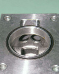
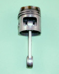
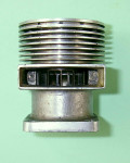
Dawson recognized correctly that the Hornet was primarily dependent upon its piston ports for its bypass entry. His tuning efforts thus focused on increasing the capacity of these ports. He began by increasing the area of the two ports in the cylinder wall, giving them a trapezoidal shape which conformed to the internal contour of the bypass passage. The two piston ports themselves were converted into a single rectangular opening which matched the combined width of the two enlarged cylinder openings.
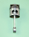
I would question the wisdom of eliminating the central dividing strip which separated the two piston ports. The main function of this strip would have been to stiffen the otherwise unsupported lower segment of the piston skirt against cyclic axial displacement due to friction drag. Without such support, that segment of the skirt has to resist linear frictional forces on its own without assistance. I could foresee problems with failure of the piston skirt arising from this situation.
However, things may not in fact be all that bad. For one thing, much of the central cylinder wall which would normally impose axial frictional stresses upon the lower piston skirt during the power stroke simply isn't there due to the significant enlargement of the cylinder ports. For another, the residual skirt segment below the opening is reasonably substantial, plus the corners of the rectangular opening have been nicely radiused to minimize the development of stress concentrations and potential cracking at the corners. So all may be well, although I would still have favoured the retention of the central dividing strip.
One trick that was missed was the opportunity to extend the cylinder ports upwards and thus ensure that the piston skirt port system would become fully open earlier during the power stroke rather than being delayed until bottom dead centre. Although the modified system opens at a far more rapid rate, it still doesn't become fully open until shortly before bottom dead centre. However, the area at the point of full opening is very substantially increased over that of the standard design.
The final step in the bypass improvements was the internal polishing of the bypass passage itself. The overall result was a bypass system that was clearly capable of passing significantly more mixture than the stock engine.
Cylinder Porting:
The work described above resulted in a sizeable increase in the ability of the bypass system to move mixture from the crankcase to the transfer ports. In fact, the three transfer ports cut into the cylinder wall were now almost certainly the limiting factor in terms of the engine's overall transfer capacity. This is an example of what we meant when we spoke earlier about one modification transferring the limitation point to another aspect of the engine's design.
Dawson clearly recognized this new limitation. His problem was that the design of the engine severely limited his ability to do anything about it. The rather narrow bypass passage precluded the addition of any additional openings at the sides. The sole opportunity for increasing transfer port area to take full advantage of the engine's enhanced bypass capacity therefore lay in expanding the three existing openings and streamlining their entries. Dawson did what he could in this regard.
The approach taken was to laterally widen the three openings very slightly (involving some thinning of the two bridging columns which separated the three openings to prevent ring snag) and also to extend the openings upwards to a small extent. This was done very neatly indeed. The increase in area was not huge, but anything at all represented a potentially worthwhile gain. The external edges of the three openings, including those of the bridging columns, were nicely rounded off to smooth gas entry.
The consequence of the upward extension of the transfers was of course two-fold. One, at their point of maximum exposure at bottom dead centre there was a greater transfer port area available to pass mixture. Two, the transfer period was extended by around 10 degrees of crankshaft rotation. This in turn reduced the already-small blowdown period between the opening of the exhaust and transfer ports. The tuner clearly wished to retain the standard blowdown period, requiring that the exhaust openings also be extended upwards by the same amount as the transfers. Both transfer and exhaust periods were thus increased by a similar margin—a perfectly appropriate modification for an engine which was expected to peak at higher speeds.
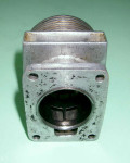
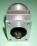
The columns separating the six exhaust openings were also thinned down, thus making a further contribution to the increased exhaust port area. The external edges of the exhaust openings were neatly rounded off as in the case of the transfer ports. It's objectively difficult to see these exhaust port modifications having much effect on performance. However, Dawson was clearly unconvinced of this—apart from the work on the ports themselves, he went to a great deal of effort to smoothly open up and flare out the internal configuration of the exhaust stack. The work is so cleanly done that one could almost swear that the case was supplied that way! Only a few residual file marks give the game away.
Disc Valve Assembly:
Here's where we find some of the more interesting features of the tuning applied to this engine! Looking first at the disc itself, this has had its forward edges nicely rounded and smoothed for more streamlined gas flow. So far so good, but there's a lot more! First, the tuner has very neatly created an annular channel near the disc hub on the opening side which has been filled with lead! The effect of this is to bring the disc more nearly into a state of dynamic balance.
Even this wasn't enough for old Dawson! The issue of drag imposed by the disc valve was clearly also of concern. To deal with this matter, the disc valve spindle was carried on twin ball races, requiring the machining of suitable housings in the backplate casting. These ball races were very accurately installed in the backplate. The front race accommodated the 3/16 inch diameter of the standard disc spindle. However, the spindle was turned down to only 1/8 inch diameter at the rear, which the rear race was sized to accommodate. This feature was forced upon the tuner by the fact that the amount of metal available in the standard Hornet backplate casting was insufficient to permit the use at this location of a bearing having a larger outside diameter.
A steel shim washer having a thickness of 0.001 inch was fitted between the disc and the front face of the inner ball race to prevent direct metal-to-metal contact between the alloy disc and the backplate, thus further reducing both friction and viscous drag. Following assembly, the disc valve was retained by a neat streamlined collar featuring a pair of Allen-head set screws—vastly superior to the soldered washer used on the standard engine. The free-running qualities of this disc valve have to be experienced to be appreciated—the thing spins forever when twirled by hand!
The internal opening of the backplate was very nicely streamlined and polished. In addition, the leading edge of the opening was cut a little wider to advance the opening of the valve by around 5 degrees. This was probably a good idea given the tuned engine's potential for achieving higher peak revs.
The standard 0.325 inch diameter venturi was clearly considered adequate, since no attempt was made to fit a venturi having a greater internal diameter. In the interests of suction and general handling, this was probably a good idea. Moreover, context is everything, requiring us to recall that by the standards of the day this was already a very substantial venturi diameter for an engine of this displacement.
Crankshaft:
The engine was fitted with the car crankshaft which lacks the square-on-shaft prop driver keying found on the aero version and also has a shorter threaded extension for flywheel mounting. No matching prop mounting hardware was included in the set of parts, leaving it uncertain how the engine was to be used. I made a simple split-collar bobbin prop driver and sleeve nut to allow the engine to be run with an airscrew.
The two ball bearings which support the crankshaft had been upgraded from the standard MRC shielded items to high quality open-cage Fafnir bearings which were assembled to the very close C-1 specification. The shaft rotated extremely freely in these bearings. Moreover, the elimination of the shields doubtless improved bearing lubrication substantially. I've never been a fan of shielded bearings, particularly in the rear race position.
The crankdisc of the shaft was polished all over, a step of doubtful performance value in my book. The one modification of substance was the drilling out of the crankpin at the rear to a depth corresponding with the rear of the rod bearing. The stressed section of the pin was unaffected by this work. The intent here was clearly to improve counterbalance by removing a little weight from the crankpin side, albeit by a very marginal amount. Dawson obviously had a thing about balance, as witness his efforts with the disc valve!
Cylinder Head:
The final modification was the addition of six extra head screws to retain the otherwise standard cylinder head, giving a total of twelve. This seems to represent an effort to improve the security of the seal between the head and cylinder. I have to say that it was probably unnecessary—I've never experienced problems with the standard six-screw Hornet head. Still, this was a not-unreasonable reaction to the likelihood of increased cylinder pressures as a result of the tuning.
Summary:
The result of all this carefully carried-out work was an example of the Hornet 60 which had a significantly greater bypass capacity than the stock model as well as extended exhaust and transfer periods. Induction capacity was also marginally improved. In addition, the engine featured slightly improved balance and somewhat reduced friction. Objectively speaking, one would expect this unit to show a measurable improvement in performance over a standard example, particularly at the higher end of the speed range.
The owner clearly had a specific application in mind, since the mounting lugs have had one extra hole apiece drilled into them. Otherwise, the engine as rebuilt remains in excellent condition.
Post-war Hornet 60 with Bulge Bypass Conversion Kit
As noted in our original article on the Hornet engines, the fact that the Hornet was no longer competitive as of late 1948 was not lost upon Hornet manufacturer Ray Snow. His response to this situation was the early 1949 release of a hop-up kit which could be fitted retroactively to existing Hornets. For reasons which are now obscure, new engines in this form were never offered by the manufacturers. The most logical explanation for this anomaly would be that the actual production of complete engines had ended by this time. However, we simply don't know for sure. The manufacturers did offer a service whereby they would install the kit on a customer's engine for a specified fee.
Having looked earlier at how an individual owner approached the task of squeezing more out of the basic Hornet design, the fact that we have access to an original Hornet hop-up kit which was in the process of being installed on an engine affords us the opportunity to see how the engine's designer Ray Snow approached the same challenge. It's clear that like others before him, Ray had recognized that the Hornet's transfer capacity was a limiting factor. The difference was that as a manufacturer he had options that were not open to ordinary modellers.
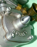
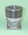
The central element of the Hornet hop-up kit was a new upper cylinder casting featuring a far larger exhaust stack (internally very much along the lines of the modified unit featured on engine number 980) and a Dooling-influenced bulge bypass which extended the annular width of the bypass at the transfer port location. Since this component was designed for use with the standard Hornet case, the original Hornet's direct connection between the crankcase and the base of the bypass was maintained together with the use of piston ports as before. The chief effect of the bulge at the top of the bypass was to extend the bypass further around the cylinder wall at the front and rear at transfer port level. To take full advantage of this, it was necessary for the owner to create two additional transfer openings in the stock cylinder liner, one each at the front and rear, bringing the total up from three openings to five.
Along with this went a revised lightweight piston. The kit was completed by a modified backplate and carburettor assembly. The standard disc valve was used in conjunction with the upgraded backplate, necessitating its removal from the standard backplate. This involved the melting of the solder which secured the retaining washer at the rear of the disc mounting spindle. Naturally, the washer had to be re-soldered in place following the fitting of the disc valve into the revised backplate.
The revised carburettor assembly was secured to the modified backplate using two 2-56 screws, thus eliminating the installation issues formerly arising from the original screw-in arrangement and permitting the machining of the component from aluminium alloy as a single piece. The exterior of the disc valve spindle bearing was externally turned down to create room for this revised component. The venturi bore was now 0.375 inches as opposed to the 0.325 inches of the standard component. The engine's high speed induction capacity was thus significantly increased.
The bulge bypass version of the Hornet used the standard cylinder liner with the addition of the two extra transfer ports, together with the standard lower crankcase casting. Timing was thus unchanged. The consequence of the modifications was that the area of the transfer ports was significantly increased while the original access arrangements from the main case to the bypass passage remained unaltered. This is actually a little odd since, as we saw earlier, these provisions were a little on the marginal side even with only three transfer openings as originally designed. The fact that both transfer port area and induction capacity were so significantly increased would appear to have more or less guaranteed that gas access to the bypass passage would become the limiting factor in the engine's breathing capacity at high speeds.
Regardless, the kit came with full installation instructions, including directions for creating the two extra transfer ports in the cylinder liner to take full advantage of the increased bypass capacity. The installation of this kit was quite credibly claimed by manufacturer Ray Snow to raise output to 1.22 BHP @ 18,000 rpm using suitable fuel with glow-plug ignition (for which the kit was evidently intended given the general adoption of this form of ignition by mid 1949). While not matching either the Dooling or the Series 20 McCoy, this was still a relatively competitive level of performance which would certainly breathe new life into old Hornets. Indeed, a well-prepared Hornet equipped with this kit was the first engine to break through the 150 mph barrier in control-line speed, although this record was almost immediately shattered by the Dooling 61 and later beaten also by the McCoy 60 Series 20.
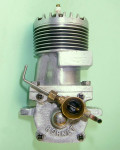
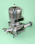
The stock of Hornet items received from Zack Smith included a complete original Hornet hop-up kit on which Dawson had started working but never completed. Based upon the absence of screw-head witness marks, the kit components never appeared to have been assembled onto an engine. I was able to make good this omission, resulting in the creation of a fine example of the "bulge bypass" Hornet. The engine bears no serial number—presumably the case was either a replacement or a pre-war item. There was also no timer, indicating that the owner's intention had been to operate the engine as a glow-plug model, as seemingly expected by the manufacturers. I have since obtained a replica timer to complete the engine, although it would appear that the kit was primarily intended all along for glow-plug operation as illustrated.
We saw when discussing engine number 980 that Dawson had clearly recognized the Hornet's major underlying weakness—an overly-constrained bypass capacity. We've also pointed out that this issue was exacerbated by the fitting of the bulge bypass cylinder with its five transfer openings in place of the previous three. The provision of this very large transfer area along with the larger venturi bore meant that the bottleneck in the engine's gas flow arrangements very definitely shifted to the bypass entry.
We also drew attention to the fact that an obvious design flaw in the Hornet as delivered was the fact that the piston ports were only in perfect register with their cylinder-wall counterparts at bottom dead centre. In an ideal world, these ports should be fully open well before bottom dead centre and should stay fully open for some time so that the bypass entry does not become the bottleneck in the system at any stage of the transfer cycle. An efficient system should be able to supply the transfer ports with all the mixture that they can handle at any given point in the cycle. In actual fact, at the point where the transfers begin to open the standard Hornet piston ports are less than half-way open—not a recipe for the most efficient employment of the increased transfer port area!
By the time that he began work on the hop-up kit, Dawson had clearly recognized this issue. To address this deficiency, he extended the cylinder ports upward, this time keeping an oval "race-track" form with no sharp edges to create stress concentrations. He also extended the piston skirt ports downward, again retaining a matching oval form. The result was that when the five transfer ports began to open, the piston port system was already wide open and only got wider as the piston continued to descend. At all stages of the cycle, overall bypass entry area was greater than the total area of the five transfer openings, thus presenting no limiting factor with respect to gas movement from the case to the cylinder. At first sight, a very rational and worthwhile improvement.
The downward extension of the piston skirt ports would have left the lower piston skirt greatly weakened if the central dividing column had been removed as it had been with the earlier model. Wisely, Dawson left this column in place when tackling the new project. I would anticipate no reliability issues with this modified piston.
The backplate was of course the revised "kit" version incorporating changes in the basic casting which permitted the attachment of the big-bore venturi with a pair of 2-56 screws in place of the former screw-in arrangement. It must be said that this was a far more satisfactory arrangement than that used on the standard engine. Dawson had got as far as re-fitting the disc valve to the replacement backplate and had re-soldered the washer to the spindle. For added security, he had also drilled and tapped the centre of the spindle and fitted a retaining screw with its own washer.
In all other respects, the engine was a stock Hornet 60. All of the working parts appeared to have done some running with the engine in its original form prior to the unit being dismantled for the creation of the revised porting and the fitting of the kit components. It's possible that Dawson would have done more if he had carried the project through to completion—we'll never know. Regardless, the result is what should be a very free-breathing example of a bulge bypass Hornet. I would objectively expect a pretty good performance from this one!
This engine was fitted with the aero shaft with its squared-off section for prop driver keying. It retained the original steel prop driver, but I made up a bobbin driver to match the shaft, putting the engine into the speed model aircraft configuration in which it is seen in the photos.
Conclusion
Looking objectively at the above modifications described above, there's no doubt in my mind that both the tuned engines would out-perform the stock model by a substantial margin. It was my original intention to evaluate this impression by presenting the results of a comparative test of the two tuned engines against my bog-stock post-war Hornet 60 no. V3318. Sadly, the time pressures which Ron and I now face in getting this and similar information up there while the opportunity remains open have precluded this.
That said, if time and opportunity permit as we move forward, I'd like to add a comparative test report to this article—it remains high on my list of things to do. For now, the above information will have to suffice. Hope you found something of interest here!


