Hope Engines Chapter 3
The Super Hope 60
by by Allan Strutt (Introduction and Addendum by Adrian Duncan)
March, 2005
Revised:
February, 2011
 |
 |
|
Click on images to view larger picture.
|
|
The existence of Hope's late 1940's entry into the then very competitive world of 10 cc racing engines is perhaps the best-kept secret of them all in the context of the Hope range. In our introductory chapter we discussed the background to the early post-war Japanese preoccupation with engines of this type. It's now time to take a detailed look at Hope's contribution to this very interesting phase in the history of Japanese model engine manufacture.
The Super Hope 60 is extremely rare today, and we are indeed fortunate that Alan Strutt owns a fine example of one of these engines. There could be no-one better qualified to share the story of this model with us, and accordingly we'll hand the pen to Alan at this point.
On January 20th 2004, something happened of great significance for students of the history of Japanese model engines. On that date, two Super Hope 60 model engines - the rarest of the rare - were unveiled to the modern world together for the first time since their departure from their native Japan. The event in question was the sale in London of the all-encompassing model engine collection of the late Miguel de Rancougne - one of the world's great collections.
In his travels around the world, Miguel found many interesting engines; and so it was that he discovered - in relatively recent times - a cache of Super Hope 60 engines from the 1940's lying forgotten in a Tokyo model shop. He found at least two spark ignition engines and at least one glow ignition variant, all of which became part of his collection.
"Super Hope 60?", we hear you say. "Surely you mean Super Hope 29...you know, that Japanese copy of the K&B of the early 1950's, when Hope were trying to forge themselves a share of the already declining market for model engines in the US and to a lesser extend Europe".
The answer is most definitely "No! The Super Hope 60 racing engines were a breed apart that - in the hands of Japanese modellers - were designed to take on the best of the US products then being used by American GI members of the post-war Occupation Forces in model flying contests held in Japan."
As the memory gears up, the next comment can be taken as read, "Oh! Okaay! You mean one of those McCoy 60 clones, like the Japanese Super Devil and the Nordec's in the UK". Again the response has to be a resounding, "No! No! No! The Super Hope 60 was a unique design which was created to raise the image of Japan by showing the occupying forces what it could do while it endured the unendurable. As if giving the finger to the world, the makers even painted these engines with what must have been left over khaki paint, giving then a remarkably militaristic appearance".
"OK - You win! So tell me about these wonder motors!"
Well, no one could really argue that they were wonder motors, but nonetheless they are definitely highly individualistic engineering creations to be proud of. Despite what must have been the very limited means at their disposal, the engineers at Hope Engineering decided to make a small number of special racing engines to the very highest quality standards for the use of their most capable home fliers.
It is true that the Japanese were talented copyists who could, and did, create exact replicas of Western products when they had a mind to do so - the Raku Shin is an exact copy of the Junior Motors Brown Junior, for example, albeit with a better timer than ever graced a standard Brown. It's also true that the Hope engineers must have been aware of the general direction that competition engines in the West had taken from the late 1930's, either by seeing the engines in the metal or having them described to them.
However, while it may be fair to describe other Japanese engines of the period as clones, to describe these Super Hope engines as either clones or copies is to deny their essential Japanese nature. Only if we were to accept the concept that a super sports car of today is a copy of a Ford Model T in that it has four wheels could we could legitimately argue that the Super Hope 60 is a copy of a 1930's Edgar Westbury design or a later McCoy in that it employs a front housing, a central block, and a rear housing that incorporates the induction mechanism.
The front housing of these engines - whether destined for spark or glow ignition - is based upon the same sand casting, which is machined nearly all over. It is designed to accommodate the two ball races that support the crankshaft. The front ball race is retained in place - and kept free from the ingress of casual dirt - by an alloy cover that screws into the front housing ahead of this bearing. The cover is tightened by a tool akin to circlip pliers that engages with two small holes lying across the diameter of the cover.
The bearings themselves are both two-row races of the self-aligning type. Machined into the front bearing housing of the cover destined for the spark ignition engine is a channel of semi-circular section, about 1 cm in length measured circumferentially. A bull-nosed grub screw that is threaded into the timer plate protrudes Into this channel. The channel and screw combine to limit the timer plate's fore and aft movement on the otherwise plain bearing housing, as well as to limit the available timing advance and retard.
For the spark ignition variant, a segment of the face area of the metal "tube" that lies between the front and rear ball race housings - with a chord equal to the diameter of the tube - is machined away; thus providing the cam follower with access to the crankshaft. At this location, the crankshaft diameter is modified so as to produce a smooth-edged cam profile.
The crankshaft itself is a fairly lightweight item, machined in one piece. A hole is drilled down its centre line to lighten. The thickness of the circular crank web is relieved so as to form a modest counterweight opposite the crankpin. At the location of the crank pin, a hole is drilled through the web into the crankpin, so this latter item is partially hollow. The end of the crank pin furthest from the crank web is reduced to a rectangular bar to engage with, and drive, the rear induction disc.
Typical of many Japanese engines of the period, a hole is drilled and tapped into the centre of the front of the crankshaft. The propeller driver (with knurled face) is turned from aluminium and push-fitted onto the shallow taper that exists between the end of the bearing journal and the propeller shaft. The front washer is steel and the propeller-retaining nut is typically made of brass.
If any legitimate criticism can be levied against the design of this engine, it is the relative weakness of the front housing in the spark ignition variant that results from the creation of the access for the cam follower. If the front of the engine were to hit the ground at all hard, it is difficult to believe that it would survive unbroken. This raises the possibility that this engine was in fact destined primarily for car use (then very popular). The tapered length of the crankshaft noted above would probably afford enough grip to secure a flywheel. The glow variant suffers no such weakness as the metal "tube" between the ball bearings referred to above has been left whole.
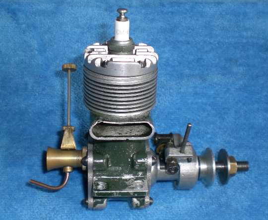
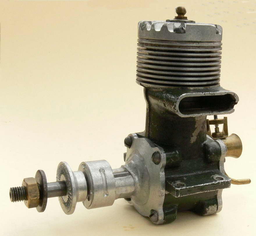
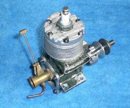
The central block is based upon a substantial sand casting that incorporates the main crankcase housing, cast exhaust stack and integral cylinder fins. The quality of this casting is good, as no imperfections are visible in the thin cylinder fins which run deep into the casting. Internally, the casting is extensively machined: the swell of the externally visible bypass has been machined internally by a circular cutter offset from the central line of the cylinder bore. Despite this, the sectional area of the bypass is of moderate size for an engine of this displacement, and would therefore probably be a limiting factor to the engine's ultimate performance.
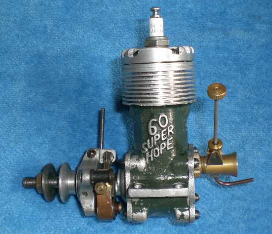
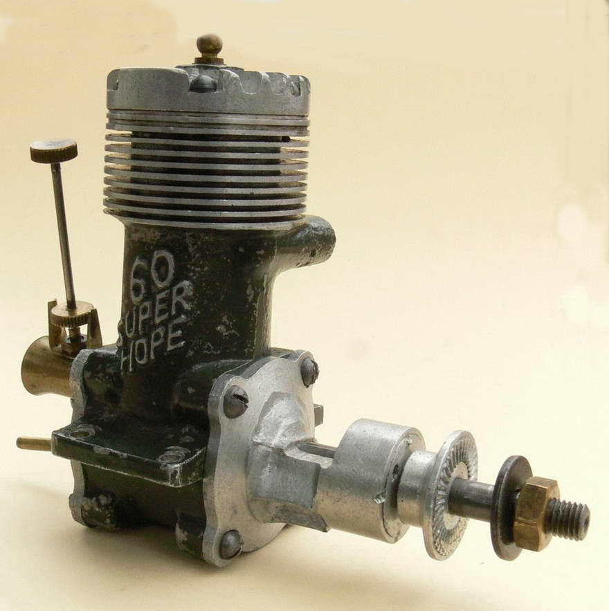
The central block is painted in dark khaki green, but this is no dab of paint added as an afterthought: the machined faces that mate with the front and rear housings are also painted in this same green. On the by-pass area the words "Super Hope 60" are cast in raised ciphers lying diagonally - the tops of the letters are relieved of paint so the words are rendered unmistakable.
A cast iron liner is shrunk into this casting, the top of this having a lip around it that sits into a complimentary space at the top of the block. The cylinder head is thus presented with a near-flat mating face which is part aluminium, part iron. However, a relatively thick aluminium gasket having the same external diameter as the cylinder at this point is fitted between the block and head.
Another typically Japanese feature is the fact that the engine uses a lapped ring-less piston. Accordingly, the exhaust port and opening for the transfer passage are sawn or milled into the cylinder walls, both of these openings being of relatively huge dimensions and having no dividing pillars. The transfer occupies approximately 90 degrees and the exhaust approximately 115 degrees of the cylinder's circumference.
The cylinder head is another sand casting, having widely spaced and very substantial fins along with a centrally mounted 10 mm plug. Internally, the head is flat with a fairly large channel of semi-circular cross-section machined into it to accommodate the piston's deflector. The resulting combustion chamber shape is not such as to promote much in the way of "swirl" near TDC, and this too may be something of a limiting factor in performance terms, as it was in the early Nordec models.
Six screws retain the head. In common with those for retaining the front and rear housings as well as those found on the timer plate, these screws are all of a round-headed slotted design (that is, with heads that are round axially with their thread, and semi-circular in side elevation, with slot heads). This design of screw is very typical of the type of fastener used by Japanese engineering concerns before and during WWII and before they were persuaded to change to crosshead screws during the 1950's. The screws typify the basic Japanese engineering ethic of the time: that just enough, was enough.
A cast iron piston is lapped into the cylinder: this has a flat top and a straight vertical deflector. The piston is of typical pre-war Japanese design in that it has very thin walls with only a slight increase in metal thickness around the gudgeon pin holes. It is a superb fit in the cylinder and endows the engine with excellent compression. While the idea of using ports cut in the lower cylinder and piston skirt to enhance or even in some cases enable gas transfer was much used in earlier Japanese engines (such as the many products from the Great Japan Miniature Aeroplane Co Ltd, and O.S.), this feature is not present in the Super Hope 60.
The gudgeon pin is a solid steel pin of 4 mm diameter, with slightly rounded ends. It floats freely in the rather short iron piston bosses. The connecting rod would appear to be a sand cast item; and can only be described as of "adequate" proportions. The casting at the big-end eye has been machined into a semi-circular shape: the big end eye is bushed with a brass or bronze-like material. In a fore and aft direction, the big-end eye extends further forwards than it does backwards so as to ensure clearance between the rod and the crankweb counterbalance. This feature was to recur in other Hope designs. The rod is approximately oval in cross-section. At the small end of the connecting rod, the width of the small-end bearing is such as to completely fill the gap between the gudgeon pin bosses within the piston.
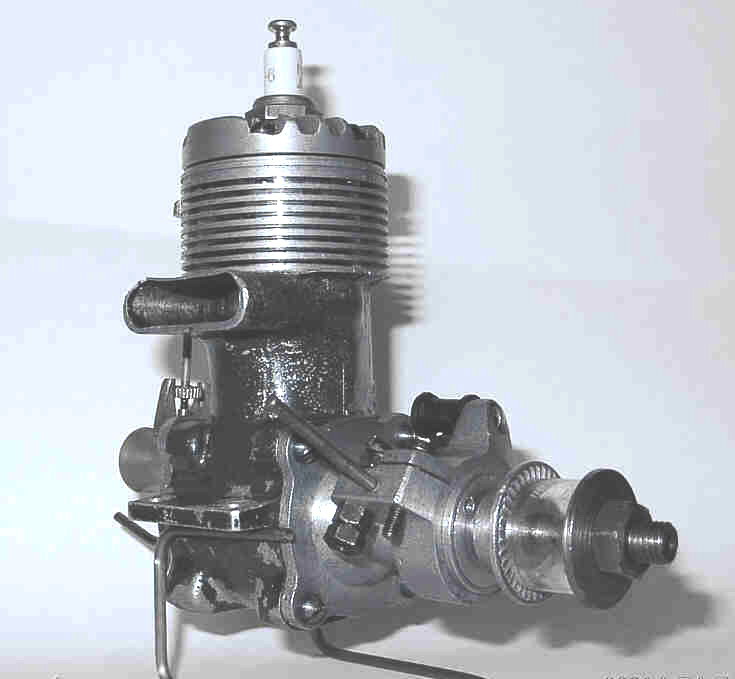
The rear housing is another sand casting. A large hole is drilled and tapped into this casting offset from the centre, into which screws the venturi assembly. The internal face of the rear housing is machined flat, and a hole is drilled through the centre of the casting along the engine's main axis. From the rear, this hole is plugged with a steel bung, leaving a blind hole in which the disc axle can rotate. The inlet aperture is left as the round hole of the venturi drilling, with no additional shaping to improve the inlet port dynamics.
The disc is made of steel and is a massive 2.6 mm thick: drive is imparted from the squared-off end of the crankpin mentioned earlier into a radial slot cut into the disc. The shape of the induction hole formed in the disc is that of an asymmetrical lozenge (note, the circumference of the disc remains unbroken). Actually, rather like that used in the ED Bee! An area opposite this induction hole has been reduced in thickness by milling, presumably as a balancing measure. At its centre, the disc has a pin or axle protruding rearwards which fits into the central blind hole of the rear housing. Very approximately, the disc begins to open at 40 degrees ABDC and is closed by 30 degrees ATDC for a relatively conservative induction period of about 170 degrees.
The venturi assembly is turned from brass (another typically Japanese feature) and is externally threaded at one end and flared into a bell-mouth at the other. A knurled brass locking ring is screwed onto the threaded end of the venturi: this allows the venturi to be locked so that the spraybar/needle valve assembly is retained in any desired attitude. The spraybar is a simple one-piece item, threaded internally to accept the externally threaded needle valve. Retention of the needle position is effected by a "U" clip of hard brass. The needle itself is of standard Japanese design of the period, with knurled brass disc for positional locking (working in conjunction with the "U" clip mentioned above) and a knurled brass disc at the outer end of the needle for the operator to grasp with his fingers.
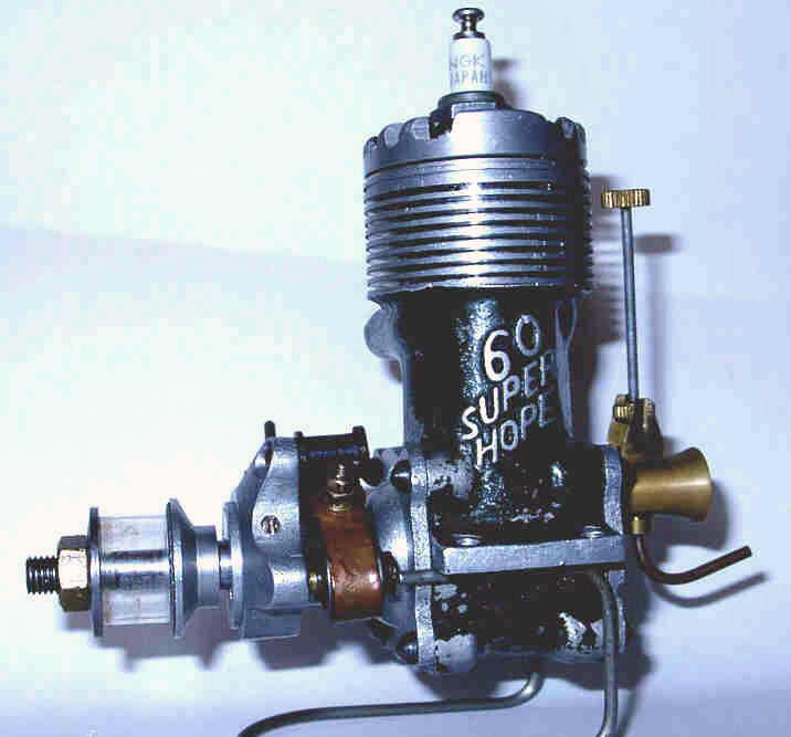
The timer assembly used on the spark ignition variant is of the open type typical of racing engines of the period wherein strong restoration springs were used for the moving point. It is mounted on a sand-cast alloy plate that clamps around the machined outside diameter of the front bearing housing. This casting has been machined all over, so very little evidence remains of it being a sand casting. As noted previously, movement of the timer plate (when unclamped) is limited by a grub screw threaded into it. Timing adjustment is effected by moving the timer plate by means of a short steel rod screwed into the plate. The shoe of the moving point is arranged to ride on the cam ground on the crankshaft as it appears in the gap between the two crankshaft bearing housings. All the screws found here are of the round headed variety described earlier.
A few specifications may be of interest at this point. The Super Hope 60 has bore and stroke dimensions of 23.5 mm and 22.4 mm respectively for a displacement of 9.72 cc (0.59 cuin), slightly below the class limit. The engine weighs 379 gm (13.37 oz.) with plug, thus being relatively light for a 10 cc racing motor of its day.
While this engine may not be a wonder motor, much care and thought have clearly gone into its design and construction. In terms of execution, the engineering is of the very highest quality and the equal of any contemporary western product - indeed, it is superior to many. There's no doubt that the creators of this fine engine cared deeply about what they were doing and put everything that they had into its design and construction. Why the Super Hope 60 did not achieve a place of prominence in the annals of competition aeromodelling remains a mystery; so one's imagination is left to roam freely in a realm wherein all scenarios are possible.
Our sincere thanks to Alan for providing us with this uniquely well-informed close-up look at one of the world's rarest model engines.
Addendum
When the above article was first published in 2009, I gratefully handed the pen over to Alan Strutt because unlike Alan I didn't actually own or have available an example of this ultra-rare engine for direct study. Moreover, given the near-unobtanium status of this motor, I had no reasonable expectation of ever doing so!
However, since the article's original appearance both Alan and I have each been fortunate enough to acquire an additional example of this very rare engine. This happy circumstance has placed us in a position to share a considerable amount of new information, hence the present detailed addendum.
These two acquisitions bring the number of surviving examples of this engine of which we are currently aware to seven—two owned by Alan, two sold from the collection of Miguel de Rancougne, two more of unknown ownership (of which David Owen kindly supplied images) and my own newly-acquired example. Six are (or were) constructed as spark ignition units, while only one was specifically intended for glow-plug operation, having no provision for a timer. As far as we are aware, none of these bears any serial number—just the "60 Super Hope" identification cast onto the bypass.
Beginning with my own new acquisition, this example came to my attention in the form of an eBay offering of miscellaneous modelling bits 'n pieces, among which was a completely dismantled spark-ignition Hope Super 60! The American-based seller was quite honest about this engine—it had a broken piston and was missing its timer plus some other bits, and he said so quite clearly. However, the rest of the major components all appeared to be there and I reckoned that I should be able to cobble up a replacement piston. Accordingly, I decided to enter the bidding.
This was admittedly a bit of a flier since there was no assurance that the engine could in fact be successfully restored. However, I reasoned that this might prove to be the only opportunity that I'd ever have to own one of these very rare motors. At the very least, it would undoubtedly provide an opportunity for further study. So after a sturdy tussle with a surprising number of other bidders, I finally completed the transaction successfully.

When the engine arrived along with a bunch of other stuff in which I had no interest, I immediately set to work cleaning up the parts and taking stock. It turned out that I'd done about as well as might reasonably be expected—most of the key components were not only present but were in extremely good condition. There was evidence that the engine had done some running in the past, but not all that much—the lugs only bore faint evidence of a test-stand mounting and the underside of the head was only lightly discoloured.
The major issues were the fact that the piston had somehow been completely shattered and the timer was missing. In addition, 6 of the 14 original M3.5x0.6 assembly screws were also missing, as were all the gaskets. But everything else was there and in near-new condition. So far, so good.
Interestingly enough, the front housing of this engine shows absolutely no evidence that a timer was ever mounted, nor does the cam face show any signs of ever having been subjected to the rubbing of a cam follower. It is actually possible that this example never had a timer and was supplied at the customer's request for use in glow-plug form at a time when the company had not yet decided to produce a modified variant specifically for glow-plug operation with no provision for a timer. There's simply no way of knowing for sure.
The complete destruction of the piston was a bit puzzling. There was no evidence of a disintegration failure during operation—pistons don't fragment in this comprehensive manner while running, and in any case a failure of this magnitude would undoubtedly have left its mark on other components. It looked more as if the piston had somehow been crushed while out of the engine. It's possible that a previous owner had set out to modify the motor and had tried to hold the piston directly in a lathe chuck or (shudder!) a vice! Or perhaps he simply dropped it and then stepped on it! The piston in these engines is of cast iron and has extremely thin walls, so it would not take kindly to such treatment. Most likely something like this occurred, upon which the owner gave up but thankfully kept the remainder of the engine components together in one box.
Some of the shards of the broken piston were lost, but enough was left to allow me to obtain most of the major measurements. However, none of the crown was present, and hence I had no way of knowing the precise height of the crown nor the dimensions and location of the baffle.

Once again, my good friend Alan Strutt came to the rescue! Alan was kind enough to dismantle his own example of the engine to measure the piston for me. A friend indeed—thanks, mate! I made a quick 'n dirty aluminium mock-up just to check that my engine was compatible with Alan's dimensions (which it was), and then I was able to make an accurately-fitted replica cast-iron replacement. Although I machined this down to logical limits as per the original, it still ended up weighing all of 17 gm—a lot of metal to shift back and forth, especially when compared to the McCoy 60's piston weight (with rings) of 11 gm! I took a lot of care with the fitting, and the compression is now excellent, although the piston could use a little running-in.

When assembled, the top of the cylinder in this design is deeply recessed into the upper crankcase casting. However, the spigot beneath the head is some 0.030 in. short of making contact with the top of the cylinder when placed in position. Clearly there had to be some sort of fairly thick interface between the top of the cylinder and the underside of the cylinder head spigot.

Thankfully, Alan was able to clarify this point also. He found that in his engine there was a fibre gasket immediately beneath the head with a 0.040 in. thick aluminium spacer directly below the gasket. This spacer made direct metal-to-metal contact with the top of the cylinder liner—clearly the makers were relying on good surface finishes to create a seal at that point. Between the two of them, the gasket and the spacer more than made up the space between the head and the top of the cylinder. The required components were easily reproduced for my new acquisition.
It seems clear that the intent of this rather complicated set-up was to allow the user to vary the compression ratio through the use of metal spacers of varying thicknesses. A spacer of as little as 25 thou could be used and still provide enough overall thickness (spacer plus gasket) to ensure a seal. And of course one could go a long way in the other direction if desired. In addition, the recessed gasket is very well supported against blow-out forces. A very elegant arrangement—typical of the care that clearly went into the design and construction of this engine. With a 0.040 in. spacer installed, the compression ratio is roughly 7.5 to 1 by volumetric measurement—a bit low for high-speed glow-plug operation, but about right when running on spark.

Examination of the components of the engine revealed several significant differences between this example and that originally described by Alan Strutt. Firstly, the number of cooling fins machined into the upper cylinder jacket section of the crankcase casting is different. Alan's engine has 7 thin cooling fins between the band directly above the exhaust port and the thick upper flange in which the cylinder head installation screws are mounted. My newly-acquired example has only five fins, which are substantially thicker. So far, mine is the only example of this type of which we are aware.
Secondly, the plug thread in the cylinder head is 3/8-24 rather than the metric equivalent of M10x1.0 as in Alan's example. There was no evidence that the head had been re-tapped 3/8-24 through an existing 10 mm thread—this would leave visible traces as a result of the slight difference in pitch (24 tpi as opposed to 25.4 tpi) and would also result in a somewhat loose-fitting thread given the slightly larger major diameter of the 10 mm thread (0.399 in. as opposed to 0.375 in.). The thread in this example is a very accurate fit to a standard 3/8-24 plug, so it would appear to be the original size.
The logical inference is that this particular unit was custom-made for an American client, probably a member of the forces of occupation. This would explain both the American plug thread and the presence of the engine in the USA when later acquired by me years later through eBay.
Further differences are to be found in the bore and stroke. The bore of my new engine is 23.95 mm rather than the 23.50 mm of Alan's example—having just made a new lapped piston for it, I can state this with complete certainly. The precisely measured stroke of my engine is 22.22 mm exactly, a little shorter than the 22.40 mm stroke of Alan's engine. These figures combine to yield a displacement of 10.01 cc (0.61 cuin). It seems that this example was nominally built right up to the full 10 cc limit (actually, a fraction beyond in this instance!), which was quite in order given the fact that engines of up to 0.65 cuin were permitted in Open class competition at the time (as witness the Enya .63 cuin racing models). The slightly shorter stroke may have been to compensate for a marginally heavier piston resulting from the increased bore, or it may simply represent a measure to reduce vibration a fraction. It may even be merely incidental—"lathe operator's license".

The restored engine weighs 367 gm (12.95 oz.) with plug—a little less than Alan's example thanks to the absence of the timer. This of course is very light for a 10 cc racing engine of the period. The engine is also relatively compact by comparison with other contemporary 10 cc racing engines.
As noted in the original article, Alan's example of the Hope Super 60 did not feature the typically Japanese piston skirt ports and associated cylinder liner ports on the transfer side. However, both the cylinder liner and the remaining shards of the original piston make it clear that the new arrival did indeed have such ports, which appear to be original and not owner modifications.
I was able to confirm the location and dimensions of the piston ports from the remains of the original piston. Interestingly enough, they were very intelligently located a little further down the skirt than one might expect so that they were almost fully open when the transfer port was first opened by the piston. This means that they'd be fully open when they were most needed—to get the initial charge into the cylinder while the transfer port was still opening and crankcase pressure remained high. By the time bottom dead centre was reached they were partially closed again, but at that point they would no longer be needed anyway since much of the crankcase pressure would have been dissipated.
This feature should confer a number of benefits. The most obvious is an improvement in transfer efficiency due to the improved gas access to the upper bypass passage. However, that's by no means all—the piston ports would also improve piston cooling by promoting the flow of cool incoming mixture through the piston interior. They would also promote better lubrication of the more heavily-loaded transfer side of the piston skirt, which absorbs the side-thrust generated during the power stroke. Finally, they would remove a fraction of reciprocating weight—an important objective with a cast iron piston. Overall, this appears to be a very worthwhile improvement.

Looking at the lower end of the engine, an obvious departure from Alan's example described earlier is the use of a composite crankshaft in this example. The full-disc crankweb is radially split more or less in the middle, thus being made up of two discs set face to face in contact with each other. The rear portion carries the crankpin and counterbalance, while the front portion is a simple disc.
The method of construction is uncertain, but an educated guess can be made. There's no sign of a "seam" inside the small hole which is machined into the centre of the crankshaft, presumably to lighten it, so it would appear that the rear portion of the disc must feature a central spigot which is either force-fitted or threaded into a hollow section of the crankshaft journal. A pair of bronze rivets are used to maintain the two components in a fixed annular relationship following installation. As in Alan's engine, the crankpin is internally drilled and the crankweb countersunk from the front at the crankpin location, presumably after assembly of the shaft.
Now all of this represents a level of complexity for which there simply has to be a rational explanation. I've thought about this a lot, and the best explanation that I can come up with is that it must be related to a desire to improve the engine's balance factor. With that heavy 17 gm piston going up and down at a rate of knots, this must have represented a real issue for the designer and a significant limitation upon the engine's ultimate performance.
However, another issue with which the designer was clearly concerned was pumping efficiency. At the time, the way to achieve good pumping efficiency was to keep crankcase volume down to a minimum (no tuned pipes back then!). The Hope designer had gone to a lot of trouble to do so—the very thin and rather complicated disc valve is an example. The Super 60 has a commendably small crankcase volume and pumps with great enthusiasm when turned over without a plug—the transfer port opens with a real crack! The designer evidently wanted to keep it that way.
Geometric considerations meant that there was little opportunity to increase the size of the visible counterbalance on the web. But adding cutaways on the crankpin side in the conventional manner would increase crankcase volume. So what to do? Simple in concept—hollow out the web internally on the crankpin side. This would achieve the goal of increasing the balance factor without adding to the crankcase volume.
Fair enough, but how? Well, by making the counterbalance section of the web (with the crankpin) a separate component which can be machined from both sides! I'd put money on it that if one were to split the components of the crankweb (I'm not volunteering!), one would find two circular cavities end-milled into the invisible face of that component—one on each side between the rivets and the crankpin. This would substantially reduce weight on the crankpin side and hence increase the degree of counterbalance in the crankweb as a whole. However, it would do so without increasing crankcase volume since the two cavities would be isolated from the rest of the case. It's actually also possible that there could be similar cavities on the counterbalance side with lead discs inserted into them.
This idea is not unique—readers may recall that the K&B Series 61 and Series 64 racing engines had internally-hollowed crankwebs. In their case, however, the webs were in one piece with milled slots on the crankpin side. The slots were isolated from the rest of the crankcase through the use of a shrunk-on aluminium band around the crankweb perimeter. Same idea, though.
Naturally, without dismantling the crankshaft on this example I can't prove any of this. But the crank "feels" to be more heavily counterbalanced than its appearance would suggest, and this is the best idea that I've been able to come up with to explain the use of composite construction. If anyone has a better idea, let's hear it!
It's impossible to say for certain in which order the divergent features seen on this example and Alan's originally-described engine appeared. If I was to be asked for my opinion, I'd say that my engine is more likely than not to be the later of the two. My sole basis for saying this is that it seems to embody some degree of design progression compared to Alan's original example. In particular, I can't see them starting out with piston ports and then eliminating them from what was clearly intended to be as good an engine as the makers could produce at the time in question. The composite crankshaft too seems to be a sophisticated response to a demonstrated vibration issue if it is indeed motivated by balance considerations, as I think likely. But these are merely observations—in themselves, they prove nothing.

Apart from the above features, my engine appears identical to Alan's original example with the exception of the missing timer. The timing of the disc valve appears to be the same as that of Alan's example—around 40° after bottom dead centre to some 30° after top dead centre for a period of 170°. Cylinder port timing is also fairly conservative by racing standards—the engine features an exhaust period of around 140° combined with a transfer period of approximately 125°.
However, a few more highlights emerge from a close examination of the engine. Little details like the oil hole drilled at an angle into the big end bearing from the front and communicating with the upper (load-bearing) surface of the bearing at its centre plus the similar hole in the centre of the small end bearing leap out at one as examples of the level of attention to detail to which the manufacturers subjected this engine.
The steel disc valve is a work of art with its extensive machining for mounting and balance purposes and the straight edge on the induction aperture which keeps it wide open a little longer around top dead centre and then gives quite rapid closure. In conjunction with the generous 9.5 mm dia. intake venturi, one would expect this valve to work very efficiently. The disc is mounted on an integrally-machined 4 mm steel spigot which runs in a plain bearing in the rear cover. The number of machining operations required to produce this single component is quite remarkable.
Having just made one myself, I can attest to the fact that the piston also requires an unusually large number of machining operations and multiple set-ups. This component alone would have been an expensive item to manufacture. However, like the composite crankshaft, the twin-row self-aligning ball bearings and the carefully-engineered disc valve, the makers skimped nothing when it came to producing this engine—if a feature was considered to be functionally necessary, they included it regardless of cost or complexity!
All of this reinforces my view that this engine was probably never intended for series production in the commercial sense. Rather, it was a limited-edition "special", probably individually produced more as a manufacturer's statement than anything else with little or no consideration given to the issue of manufacturing cost. There's simply no way that this engine could have been manufactured at anything approaching a reasonable unit cost, even in late 1940's Japan.

After I made the piston, the required gaskets and head shim and the missing head screws, the engine went back together very nicely. With a 3/8 in. KLG Mini-Glow plug fitted, it looks really striking with its dark olive-green case offsetting the machined aluminium surfaces. Alan Strutt has very kindly sent me a drawing of the timer, and I hope to get around to making a replica at some point in the future.

Turning now to Alan's new acquisition, this is another spark ignition model which exhibits a number of marked departures from the construction of the other examples described so far, thus presenting us with yet another variant of the Hope Super 60. Once again, this example came from an American source along with a report that it had apparently been intended for use in something described by the seller as a "Japanese Smith tether racing car", whatever that is! The seller was unable to clarify what this meant—he was simply selling off items from an estate and only knew what he'd been told. If anyone knows what a "Smith car" is, please let us know—so far, we've come up empty!
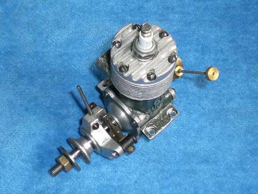
The most immediately obvious things about this engine are its pale green crankcase and the fact that it has been assembled with the exhaust stack on the left. Alan is quite certain that the colour is a repaint—it's more than likely that it was originally painted in Hope's trademark dark olive green drab.
The most unique structural feature of this example is its completely different front housing which incorporates only a single ball race supporting the shaft, and that is at the front of the bearing! This is consistent with the idea that it was intended for car service and that the bearing was included for flywheel support and resistance to spur gear loads, but the omission of a rear race is a bit odd regardless.
The crankshaft in this engine is once again completely different from that of either of the examples described above. The front diameter of the crankshaft is smaller, being threaded 6 mm instead of the 7 mm seen on other examples. It is also slightly shorter. In addition, the centrally-drilled hole in the centre of the shaft at the rear is absent. The crankweb is a one-piece item having both a counterbalance and a pair of cutaways, one on each side of the crankpin. Once again, a serious attempt to increase the engine's balance factor, albeit on this case without resorting to the trickery of a composite shaft to maximize crankcase volume.
The timer arrangements are somewhat different as well. The cam is not machined into the middle of the crankshaft journal as on previously-encountered spark ignition models, but instead is formed as an integral element of the steel prop driver.
The cylinder porting is very different from the other examples described earlier. The exhaust is divided into two "elongated circle" holes with a dividing bar between them which is located centrally in the exhaust stack. Most oddly, the transfer port consists of a horizontal row of 5 drilled holes in place of the large rectangular opening described previously. The engine also lacks the piston ports seen on my own example. Overall, it appears that cost considerations may have been a factor in the manufacture of this variant.
Further differences are to be found in the cylinder head. On this example, the head is retained by only 4 screws, which seems a retrograde move, especially when one considers the sealing problems that Mamiya experienced with their own racing 60 using only 4 screws.


On the plus side, the plug location is offset towards the transfer side, which is usually a good move with a baffle piston in that it reduces the time for the partially-isolated pocket of mixture on the transfer side of the piston baffle at top dead centre to become involved in the combustion process. In addition, the design of the under-side of the head reflects a far more sophisticated understanding of the need to promote rapid flame propagation in the combustion chamber.
The brass intake venturi is of similar construction to the others but the distance between the end of the installation thread and the spraybar is reduced. Together with the shorter crankshaft mentioned earlier, this contributes to a reduction in the engine's length of some 5.3 mm.

Overall, it must be said that this engine presents us with an odd mix of retrograde and forward-looking features. The more advanced head design suggests that it is the latest engine in the known series, in which case we might suspect that the various simplifications noted in connection with the piston, cylinder porting, head fixing, main bearing and crankshaft were cost-cutting measures. If so, this would be the first time that Hope had ever displayed any concern over cost in connection with the Super 60! It may be that they were contemplating putting this version into series production—we'll probably never know.
The really significant point about all of this is that within the group of seven engines of our present acquaintance we know of no less than four distinct variants—three spark ignition and one purpose-built glow model. This is an unusually high proportion of variants in such a small sample. The implication is that the manufacturers were not working to a fixed design. Instead they were forever tinkering with the design with a view to improving performance, or perhaps in response to individual customer requests. This reinforces our view that these engines were "manufacturer's statements" rather than production engines per se. If there were ever plans to put this engine into series production, it would seem that they came to nothing.
This brings the story of the Hope Super 60 up to date as of the present. If anyone out there is in a position to add to our knowledge, let's hear from you! All contributions gratefully and openly acknowledged!


This page designed to look best when using anything but IE!
Please submit all questions and comments to
[email protected]
|
Unless otherwise expressed, all original text, drawings, and photographs created by
Ronald A Chernich appearing on the Model Engine News web site are licensed under a Creative Commons Attribution-Noncommercial-Share Alike 3.0 License. |

|