The Bicycle-Spoke Frogs
by Adrian Duncan
 |
||
| Click on images to view larger picture. | ||
FROG (Flies Right Off Ground) was the trade name of International Model Aircraft Ltd. (IMA), who were located on Morden Road in Merton, SW 19, a suburb of London. The location was incidentally quite close to that of their soon-to-be rival engine producers ED, who were located in nearby Kingston-on-Thames and entered the model engine market in late 1946. The presence nearby of several scrap metal yards from which raw materials could readily be procured doubtless influenced the choice of location for both firms.
 |
 |
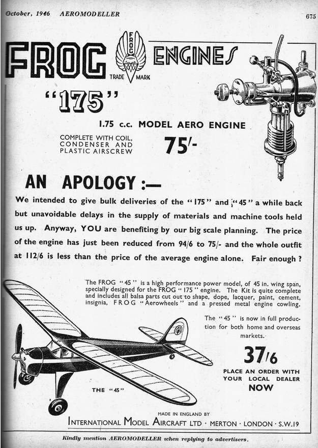 |
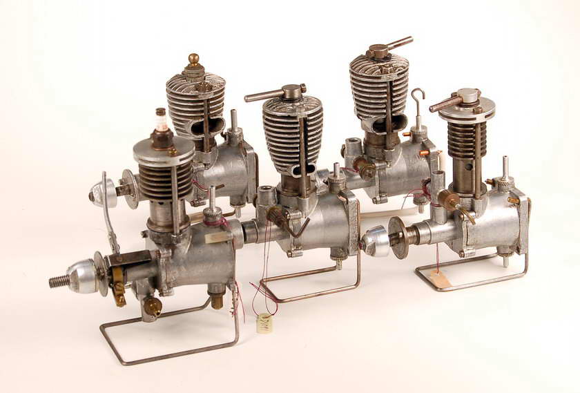
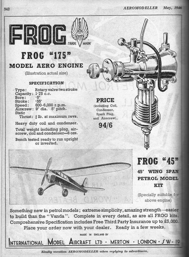
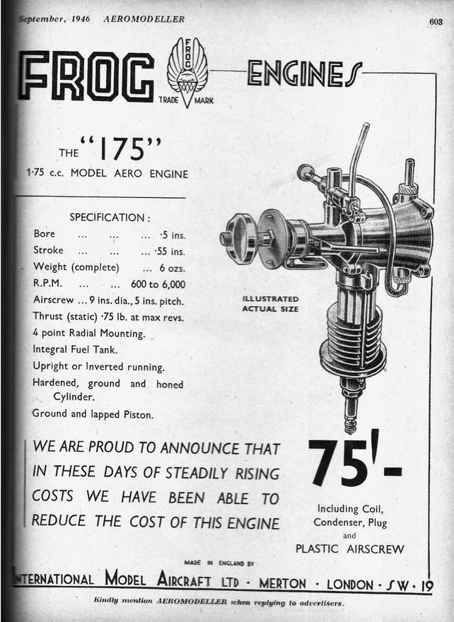
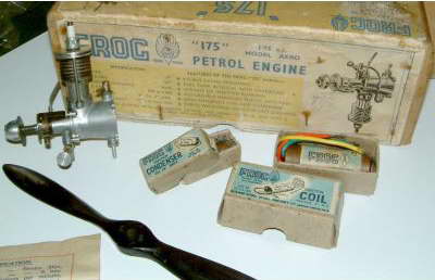
The Frog model engine range was introduced quite soon after the conclusion of WW2 with the appearance in early 1946 of the 1.75cc spark-ignition engine, known descriptively enough as the Frog 175. This was the first of a succession of Frog engines which shared the common features of a crankshaft rotary valve, a detachable front bearing housing, a radial fuel tank mount and a cylinder assembly which was held down by two long studs rather like short bicycle spokes, one on each side. These studs were threaded at both ends and the lower ends screwed into a pair of holes located on both sides of the upper crankcase. The resulting series of engines is often colloquially referred to as the "bicycle spoke" series, although the studs used are in fact quite substantial and certainly adequate for the job.
 On the original 175 spark-ignition model, the Meehanite cylinder featured a narrow circular flange near its base below the exhaust ports. This flange was machined integrally with the cylinder itself, as were the cooling fins. The lower flange bore against the upper face of the crankcase casting with a thin gasket for sealing. The protruding base of the cylinder below the flange served as a spigot to locate the cylinder in the top of the crankcase.
The two studs extended upwards past the cylinder with its flange and its integral cooling fins and through the separate disc-shaped aluminium alloy head, which was then secured by a pair of nuts which threaded onto the top of the studs and bore upon steel washers. Thus the entire cylinder assembly was held down solely by these two nuts together with their respective studs. A thin gasket was provided to create a head seal.
 This set-up naturally promoted distortion of the head and uneven pressure on the head seal due to the hold-down forces being exerted on only two points around the circumference. It also had the potential to introduce distortion of the cylinder given the fact that the hold-down forces were applied at the top of the cylinder in an uneven manner. Overall, this was a poor system mechanically speaking and one which actually argued against over-tightening of these two nuts beyond the point at which a head seal was achieved.
If carefully assembled, the set-up was undoubtedly capable of dealing with the relatively low working stresses and internal pressures imposed by the spark ignition mode of operation. However, the challenge of maintaining an adequate head seal in a configuration which by its very nature promoted distortion sometimes drove frustrated owners to tighten these nuts to the point where either the liner became distorted or the rather marginally-adequate 8BA threads at the top of the studs became stripped. This was a weak point which would receive attention from IMA in due course.
The Frog 175 had a measured bore and stroke of 12.65mm and 13.97mm respectively for a displacement of almost exactly 1.75cc. The cylinder featured four drilled exhaust ports of modest size, paired two to each side. The bypass passages were rather small milled grooves formed in pairs in the cylinder walls, two fore and two aft. Gas entry to these passages was greatly compromised by the "guillotine effect" of the piston skirt as it descended—at bottom dead centre, the lower piston skirt almost completely obscured the entry to the bypass passages. The provision of cutaways in the lower piston skirt fore and aft would have greatly alleviated this problem, but this fact escaped the IMA engineering staff. Perhaps it didn�t matter given the speed range in which the engine was expected to operate.
 The front bearing housing on the early models was secured by four rather marginal 10BA screws made of cadmium-plated brass. These were to be replaced later with steel items, as we shall see. The timer was mounted on a machined boss at the front of the main bearing in the usual manner, and the cam was formed as an integral feature of the rear of the hardened steel prop driver. This in turn was securely located on a milled square-section portion of the shaft using a matching square-section socket formed in the rear of the prop driver. The timing relationship of the cam to the shaft was thus securely fixed during use, but the position of the timer arm while running could be varied to suit different installations simply by relocating the prop driver in any one of four positions on the shaft. The original model had the intake located beneath the main bearing rather than in the more conventional upper location. The early spark ignition models did not carry serial numbers.
The conoidal tank mount was cast integrally with the crankcase and featured a sturdy square flange at the rear with four mounting holes placed at the corners. The back of the tank was a piece of stamped aluminium sheet which was pressed and then swaged in place along with some form of sealant. This component carried the maker�s identification and trade marks as well as the serial number on the later models.
Protruding tapped bosses were integrally cast into the top and bottom of the tank, and knurled plugs with small spigots for the fuel tube screwed into each of these bosses, serving respectively as the filler hole and the fuel supply point. The thread used on these fittings, incidentally, was the standard 1/4-32 plug thread. With this arrangement, the engine could be used either upright or inverted simply by switching the fuel tubing to the opposite fuel attachment point on the tank. The position of the spraybar relative to the tank suggests that the Frog 175 was expected to be operated for the most part in the inverted position, since in that position the needle and choke tube were readily accessible and the spraybar was more or less in the same plane as the full level in the tank, thus avoiding fuel loss or flooding due to gravity drip feed.
Since there was only one fuel tank vent with this system, it was necessary either to remove the (uppermost) filler spigot each time or to invert the model when filling the tank so that the fuel tube and spraybar opening served as the air vent.
 One somewhat less-than-praiseworthy feature was the use of a left-hand 2BA thread to accommodate the prop-nut. This was presumably to encourage the prop-nut to tend to tighten itself when the prop was flicked while starting, but it was an unnecessary move which really accomplished nothing other than to make the replacement of a lost prop nut a rather more serious matter than it otherwise would have been! The prop nut supplied was actually a neat aluminium spinner nut with two flats milled into the nose to allow the use of a wrench for tightening.
In early 1947 the 175 sparkie was joined by the Mk I Frog 100 diesel of 1cc displacement. Prototypes of this latter engine had in fact appeared at the Model Aircraft Exhibition in 1946, where they were noted by Lawrence Sparey (Aeromodeller September 1951 issue, test of Frog 150). The reduction in displacement was achieved entirely through a reduction of the bore from 12.65mm to 9.52mm, the stroke of 13.97mm being retained, as it was to be in all of the engines in this series.
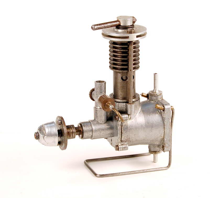 The Frog 100 Mk I diesel was generally very similar in layout to the 175, but naturally dispensed with the timer and spark plug. It also did not require the heavy ignition support system of the 175, and hence had a significantly higher effective power-to-weight ratio. In terms of its in-flight performance, the 100 Mk I was likely very little inferior to the 175 and was probably far more dependable in operation. Apart from the absence of a timer and the provisions for compression ignition, it was structurally very similar to the 175 model, retaining the tank mount, the integral cooling fins, the circular-flanged lower cylinder and the consequent retention of the entire cylinder assembly by the two nuts on top of the studs. The head seal in this case was of course provided by the contra-piston, so the issue of over-tightening of the nuts to ensure an adequate seal naturally did not arise—the head only retained the function of accommodating the compression screw.
One change which was applied to the Frog 100 diesel from the outset was the relocation of the intake from below the main bearing to its more conventional position on top of the bearing. This was a simple matter of assembling the front bearing housing the other way up—the casting used was identical to that used on the 175, even retaining the timer mounting boss at the front of the bearing. But the shaft induction port naturally had to be re-timed to accommodate this change. I�m unclear regarding whether or not the same change was made to the 175 at this time, but it may have been—can anyone advise on this point?
The implication is that the makers must have found that most people preferred to use their diesels in the upright position, since this change brought the spraybar into the correct alignment with the "full" level in the tank when the engine was mounted in that position. It is certainly true that a diesel is far less prone to flooding and hydraulic lock in an upright configuration.
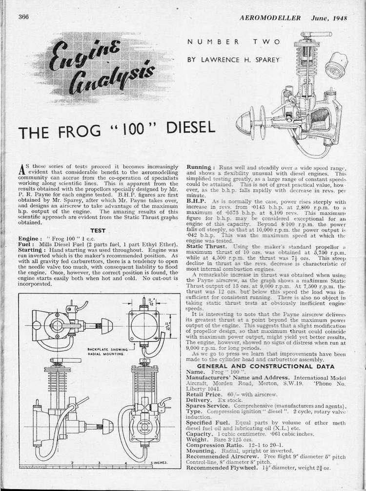
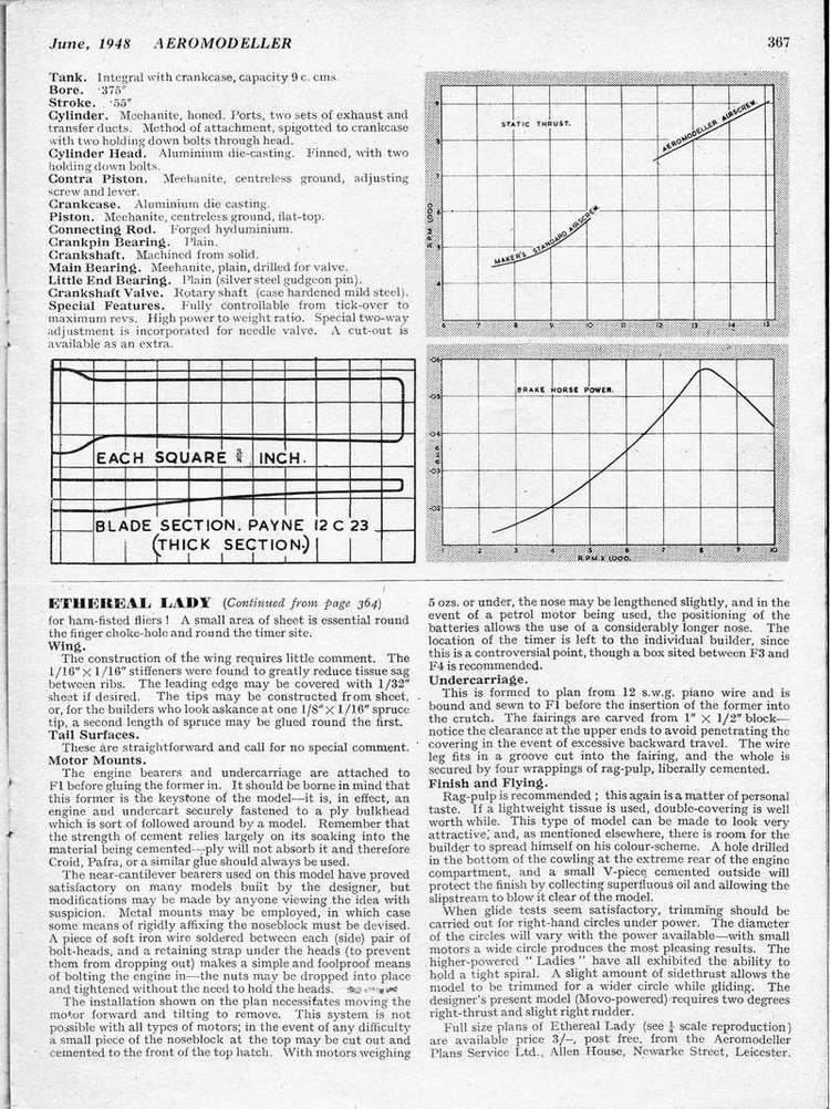 The Frog 100 Mk I was the subject of a test report by Lawrence Sparey which appeared in the June 1948 issue of Aeromodeller. Sparey obtained 0.0575 BHP at 8,100 rpm—a very good figure indeed if it was accurate! The engine clearly had plenty of low-end torque, in keeping with its long-stroke design. Bore and stroke were given (correctly) as 9.52mm x 13.97mm, making the engine very much under-square in keeping with then-current thinking regarding model diesel engine design. Actual displacement was 0.99cc and weight was reported as 3 1/8 ounces. The engine sported a neat spring between the compression vernier and the head which effectively helped to prevent compression run-back—a worthwhile feature which was carried over to the later diesel models. This engine proved quite popular and it didn�t take IMA long to grasp the potential of their little 1cc diesel. Work was put in hand both to update the existing designs and add to the range. The result of this effort was the expanded series of generally similar second-generation "bicycle spoke" Frog engines.
The first steps towards revision of the range were taken in early 1948 with the 175 spark-ignition engine, by then some two years in production. The former integrally-machined cooling fins on the cylinder were eliminated in favour of a combined cooling jacket and cylinder head of die-cast aluminium alloy which slipped over the now-cylindrical cylinder and was held down by the two nuts at the top of the studs. This unit served both for cooling and as the cylinder head, carrying the plug and sealing to the top of the cylinder with a thin gasket. Because of the finned cylinder portion below the actual head, this revised unit was far less susceptible to distortion than the former disc-shaped head.
At this stage the former hold-down system was retained—the cylinder (which at this time was still made of Meehanite) continued to be located on top of the crankcase with a narrow circular flange through which the hold-down studs did not pass, and hence the entire cylinder assembly continued to be held down solely by the two nuts at the top of the studs. Bore and stroke remained unchanged at 12.65mm and 13.97mm respectively for a displacement of 1.75cc as before, but the intake was relocated to the top of the main bearing from its former underside location. This of course required re-timing of the crankshaft rotary valve. However, it allowed the use of the same crankshaft on both the 175 and 100 models—a good move in terms of cost reduction. As noted above, this change may actually have been made some time previously on the original 175 model—I�m not certain.
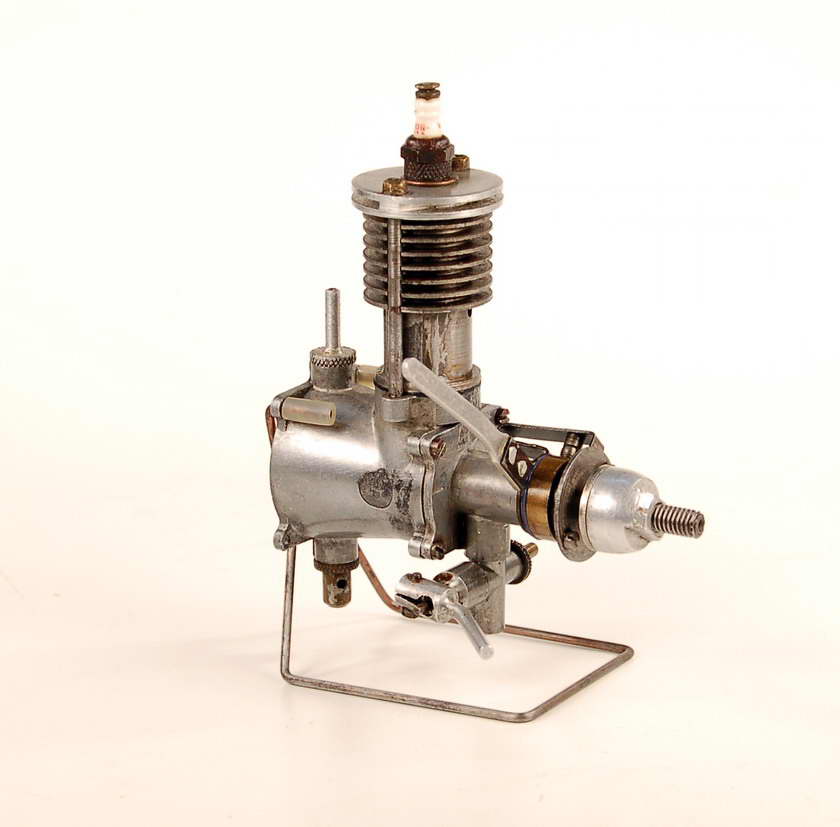
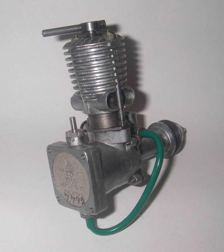
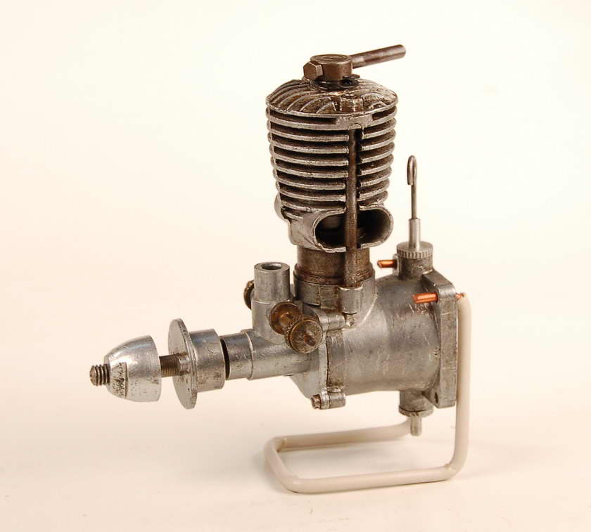
It would appear that relatively few examples of the resulting Mk II version of the 175 model were in fact made, and this version of the engine did not survive 1948 as a production item. The illustrated example has lost its timer, having been used (as many of them doubtless were) with glow-plug ignition, but the steel spark-ignition prop driver with integral cam is still present along with the timer mounting boss machined into the front casting. Interestingly, the shaft on this example has a conventional right-hand thread for the prop-nut! The shaft is unquestionably original, so it appears that IMA may have toyed with the idea of changing this rather arcane feature at some point. If so, the idea didn�t stick!!
 With the demise of the 175 sparkie in late 1948, it was definitely time to update the range. First up was the Frog 100 diesel model. The revised cooling jacket/cylinder head combination used on the updated version of the 175 was retained, but the method of securing the cylinder assembly clearly warranted further attention. Hitherto, the entire assembly had been held down solely by the two 8BA nuts on top of the hold-down studs. The maintenance of an adequate seal on the spark ignition model had resulted in frequent over-tightening of these nuts and consequent stripping of the threads. The additional stresses imposed on the system in the 100 model with its compression ignition must also have strained the capacity of this hold-down arrangement.
Accordingly, on all of the new models which were now to be introduced, the flange on the lower cylinder which located it on top of the crankcase was widened at the sides to cover the two threaded holes in the crankcase for the studs. Holes were drilled through this expanded flange, and the studs now passed through the flange into the threaded holes in the crankcase casting, being secured there by lock nuts which bore directly upon the upper surface of the flange.
The consequence of this change was that the cylinder itself was now secured directly at its base by the locknuts which bore against the flange. Hence the upper two nuts no longer secured the cylinder—that was achieved directly by the locknuts at the base. The only residual function of the two nuts at the top was to retain the cylinder head, and they only had to be sufficiently tight to do this rather than to retain the entire cylinder set-up. A neat feature introduced at this time was the use of self-locking nuts at the top of the studs to ensure that they remained in place even when not tightened all the way. There was no longer any excuse for stripped threads at the top of the studs!
In keeping with IMA�s objective of making the revised engines that little bit more sturdy, another practical change that was made at this time was the replacement of the rather soft cadmium-plated brass screws formerly used to secure the front bearing housing with far more durable steel items. However, the rather marginal 10BA thread on these screws was retained.
 A further change which was applied at this time was the modification of the crankcase/tank mount die to significantly increase the thickness of the mounting flange at the rear of the tank mount. It is unclear why this was done—the original mounting flange appeared to be quite adequate for the job. But there it was; the comparison image of the 175 Mk 2 with the later 160 makes this change very apparent.
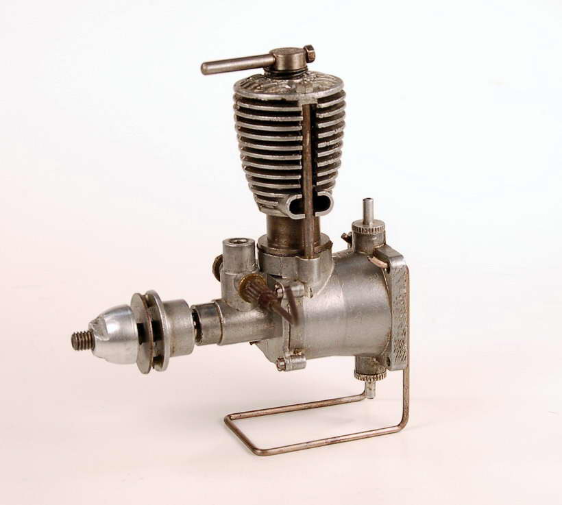
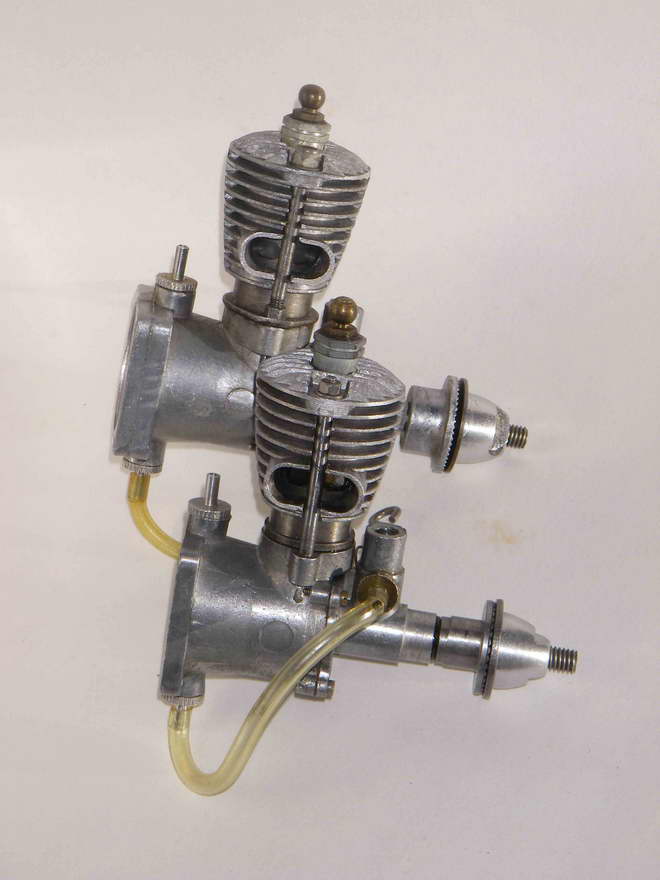
These changes were first applied to the Frog 100 Mk II diesel, which appeared on the market in late 1948 or early 1949, by which time the Mk II version of the 175 spark-ignition model had disappeared from the market. Since the lower flange now served as a pair of hold-down lugs and would thus be subject to crash stresses, it was decided to increase strength by switching from Meehanite to steel for the cylinders. The exhaust ports were substantially increased in size at the same time, and the timing of the engine was modified from that of its Mk I predecessor. However, bore and stroke remained unchanged.
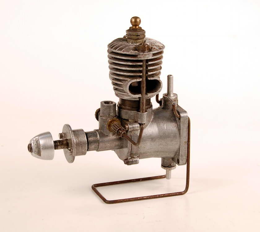
The revised engine retained the rather tall appearance which was even then becoming rather antiquated and old fashioned. To a very large extent, this was due to the extremely (and unnecessarily!) long contra piston employed. Presumably the makers hoped to eliminate leakage past the contra piston and obtain a better "feel" for adjustment by doing this. We now know that this was not necessary, and the engine could easily have been "prettied up" somewhat by making it lower (and also lighter). Weight of this engine was 3.75 ounces—quite a bit heavier than the contemporary rival ED Bee and substantially more than the previous Mk I Frog 100 model. The illustrated example weighs exactly the reported figure.
 |
 |
 |
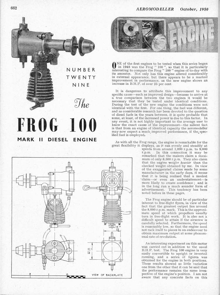
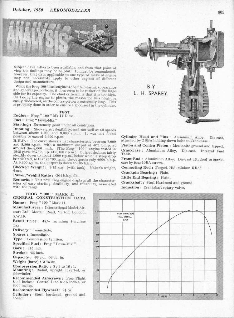
This engine too was subjected to an Aeromodeller test by Lawrence Sparey. The resulting report appeared in the October 1950 issue of the magazine, quite a while after the engine had actually been introduced. On this occasion, Sparey obtained a figure of 0.071 BHP at around 8,000 rpm. This implies that the torque of the engine had been improved over the Mk I version, because the peaking speeds were essentially the same. The figure is quite creditable, especially when we consider that Sparey�s October 1949 test of the rival ED Bee had yielded only 0.062 BHP, albeit at a higher speed of 10,600 rpm. The Frog clearly had substantially more torque than the Bee, assuming that the test methods used were essentially consistent. No doubt its long-stroke design had much to do with this. Note that the green plastic fuel tubing seen in the photos is original; the engine shown is LN (like-new), un-mounted and apparently un-run.
 IMA didn�t stop there with their 1949 models—they also launched two larger engines based once more upon the same crankcase casting and lower-end components. The first was another diesel—the 180. This was structurally identical to the 100 Mk II, even down to the use of the same crankshaft and main castings. The stroke remained unchanged at 13.97mm, but the cylinder was made larger in external diameter in order to accommodate the increased bore of 12.70mm, bringing the engine far closer to a square bore/stroke configuration and raising the displacement to 1.77cc, fractionally greater than that of the then-defunct 175 spark ignition engine (as the name would suggest). The engines continued to share an unusually high proportion of common parts, which must have really helped to keep costs down. The designer took advantage of the larger cylinder to provide substantially greater port areas, thus allowing the 180 to breather far better than the 100. A revised cooling jacket casting was necessarily used to drop over the larger cylinder and provide adequate cooling.
The genius of this move lay in the fact that since the two models used essentially identical lower castings, their mountings were interchangeable. Thus a 100 owner wanting more power for his creation could simply buy a 180 and bolt it in! The weight of the 180 was 4 ounces exactly—only one quarter ounce more than the 100. This could easily be accommodated by trimming, and the slight additional weight was more than compensated for by the added power. The 180 was never tested as far as I am aware, but I can confirm from personal experience that it is a far more powerful engine than the 100.
But even this wasn�t enough for IMA—diversity of their product line was the thing! As of 1949, increasing attention was being paid in England to the potential of the glow-plug motor, and a number of British manufacturers were even then experimenting with this form of ignition. The Yulon range of glow-plug engines had already achieved great renown. ED had included a glow conversion kit with their 2.49cc Mk III front rotary engine introduced in early 1948, and were to offer a glow conversion kit for its 1951 replacement, the 2.46cc ED Racer. Amco offered a glow conversion kit for their highly-regarded 3.5 plain bearing model introduced in 1949. At the same time, ETA were launching their famous 29 glow-plug model, and even Allbon were about to release their 1.49cc Arrow. And IMA must surely have noticed that a lot of people were operating their Frog 175 models on glow-plug ignition in order to eliminate the dead weight of the ignition system—the illustrated Mk 2 example is a case in point. The sun appeared to be rising upon the glow-plug engine in Britain. Could the manufacturers of the Frog range remain aloof from this?? Not at all!!
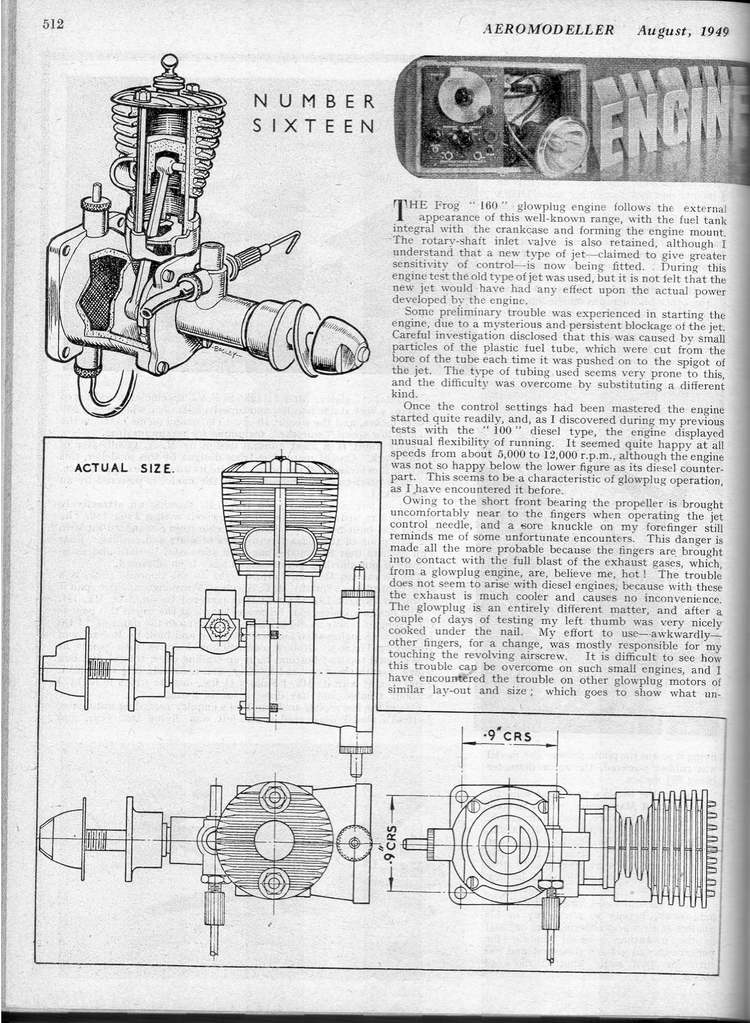
 So the next step in the "bicycle spoke" saga was the introduction of the 160 glow-plug version of the basic Frog design. This was in effect a re-configuration of the Mk 2 version of the 175 spark ignition engine, and like all the rest it shared the lower end components of its two contemporary relatives. Hence stroke was unchanged at 13.97mm but the bore was slightly reduced from that of the 175 to 12.32mm, giving a capacity of 1.66cc instead of the former 1.75cc. It�s hard to see why they did this—the cylinder is simply a 180 item that has been slightly under-bored and shortened. The full 175 or even 180 bore could easily have been accommodated, albeit with a somewhat thinner cylinder wall. Perhaps it was a desire to provide a thicker seat for the cylinder head which led to the slight reduction in the bore. But it appears more likely that IMA anticipated that,with its glow-plug ignition, the 160 might attract some interest in the USA and that a reduction in displacement to the American standard of 0.10 cuin therefore made sense.
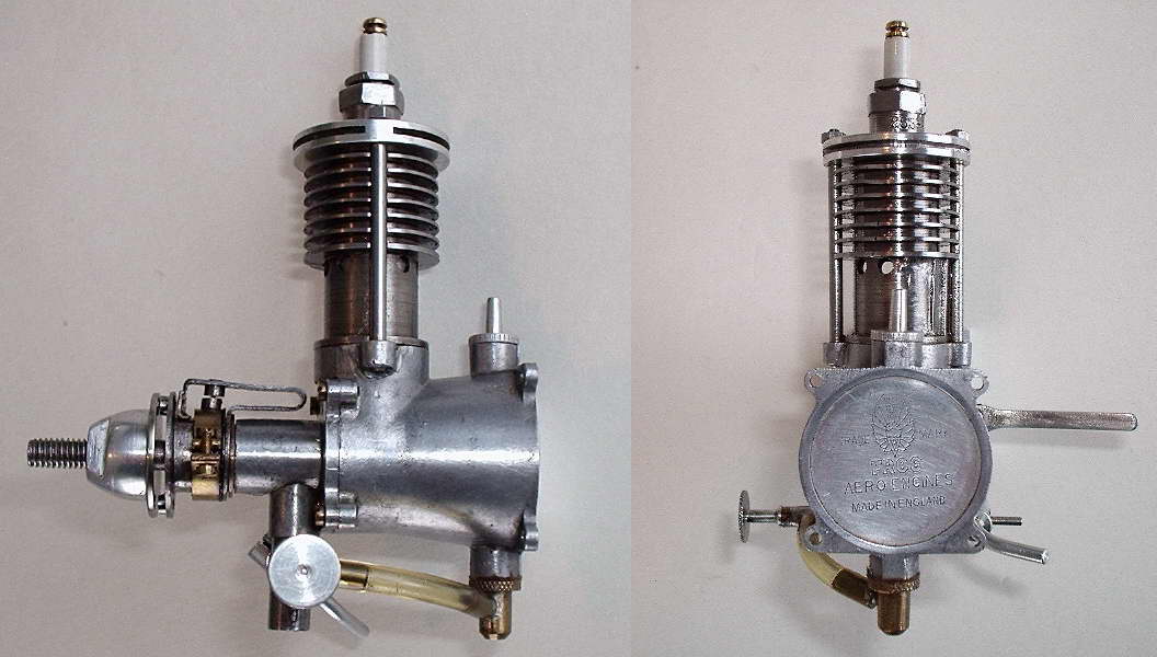
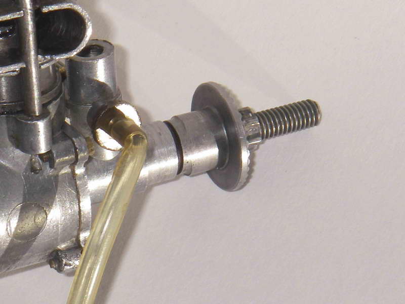
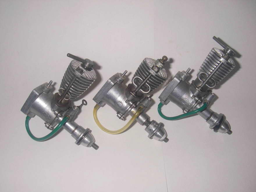
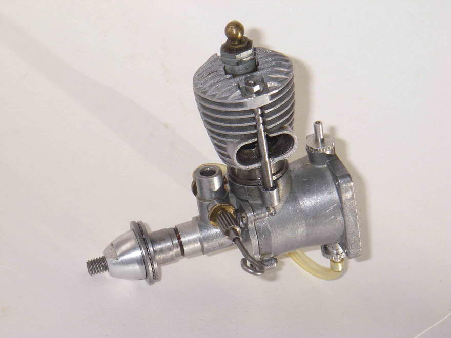
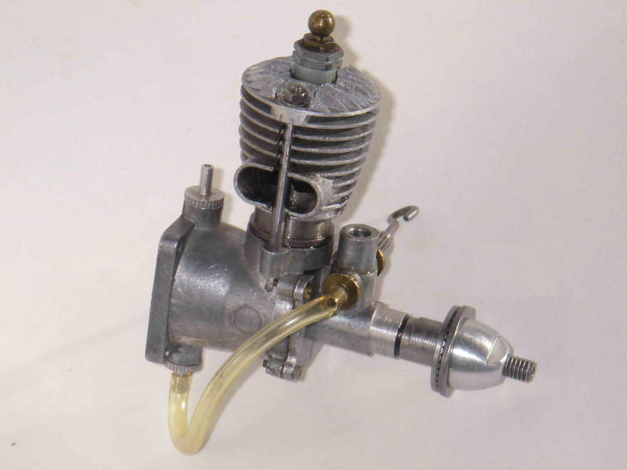
The cooling jacket employed was identical to the one formerly used on the revised 175 spark ignition model (no need to produce a new die), and this sealed as before with a gasket on the top of the liner, which of course had no contra piston. The revised system for cylinder retention was naturally retained, with the cylinder being secured at its base using lock-nuts on the lower stud threads. The absence of the contra piston naturally reduced the height of the engine and gave it a far more "compact" look. The steel prop driver with its cam was no longer necessary, and hence the 160 used the revised cast aluminium alloy item employed on the two revised diesel models. This can be clearly seen in the attached images. Note too that this engine used conventional transparent fuel tubing—presumably the green plastic tubing used on the diesels couldn�t handle glow fuels?!?
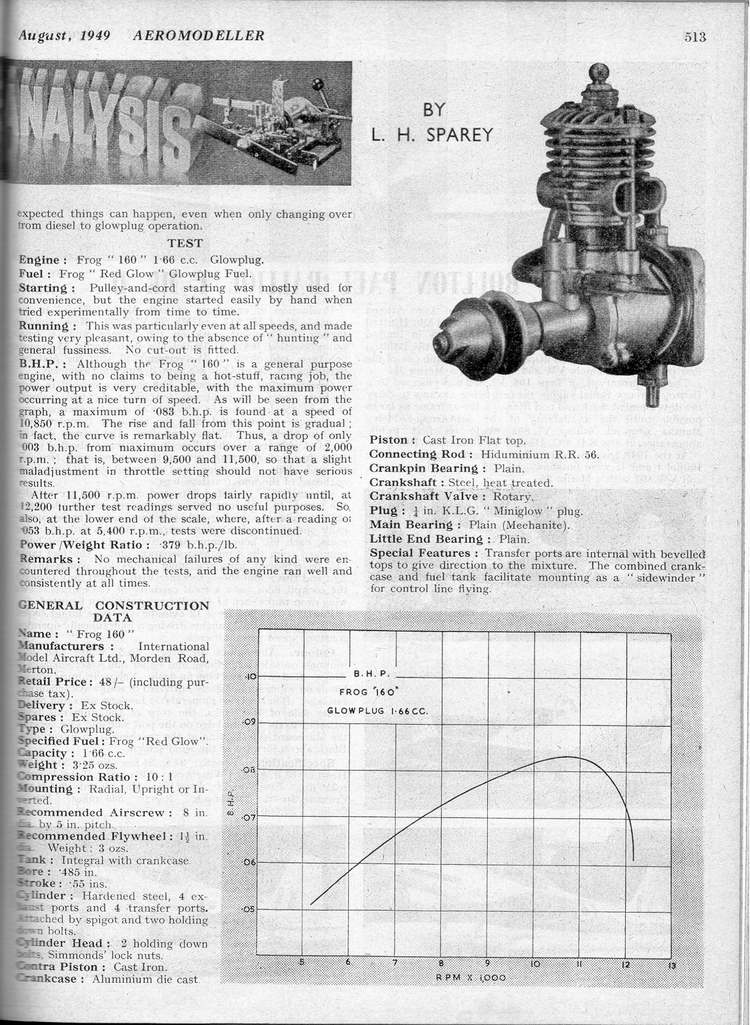
 The 160 could certainly have used any help that it might have got from the use of a larger bore!! The engine was the subject of yet another test by Lawrence Sparey, which appeared in the August 1949 issue of Aeromodeller. Sparey praised the handling of the engine to the skies, but could only extract 0.083 BHP from it, albeit at the relatively high speed of 10,850 rpm. This was of course on Frog Red Glow fuel—a very low nitro mix indeed, if in fact it had any nitro at all. As a low-compression engine, the 160 would doubtless have done far better on a fuel with a bit of nitro in it!
The power reported by Sparey is of course very little greater than the power obtained a year later from the 100 Mk II diesel (see above), but the power is greater(!) and the engine is lighter and more compact as well despite its greater displacement. It only weights 3-1/2 ounces—a saving of a quarter of an ounce over the 100 diesel and half an ounce over the 180 (Sparey reported a weight of 3-1/4 ounces, but mine weighs exactly 3 � as illustrated). So here was yet another option for our friend the Frog 100 owner—he now had the option of replacing his 100 diesel with a lighter glow engine that produced a bit more power by way of a bonus! And the weight difference was small enough that trimming would be pretty easy. Again, good marketing prospects in play!
 |
 |
IMA must have liked the results of the 160 glow program, because later in 1949 they introduced the first model of their famous and very successful 500 glow engine. This was clearly based on the then-current K&B Torpedo 29, but was a very worthy production nonetheless.
The Frog "bicycle spoke" range continued in production into 1951, but was by that time beginning to look positively antiquated, and it was in that year that the series met its demise, to be replaced by a new range of updated Frog engines which began with the 150 diesel, a thoroughly up-to-date design in all respects.
Based on my own experiences (I have owned, and still own, a number of examples of most of these engines), I can confirm that they are very easy indeed to start. The very small crankcase volume doubtless helps here. They also run very consistently. The 180 is far more powerful than either the 100 or the 160—if you built a model for either of those two that proved to be underpowered, this was a complete answer!! The illustrated incomplete 175 spark ignition model runs very well in glow-plug form.
 A few comments about the engines from a practical standpoint, based on my own direct experience. First, if planning to test-run one of these, first make sure that the retaining nuts at the base of the cylinder are reasonably tight when the head nuts at the top of the studs are also snug. Damage can result if any of these nuts are loose, and they should be re-checked after a few runs. But do not over-tighten! If you strip any of the threads, the engine is useless. Mind you, the threads in the case lugs are full depth and are fully utilized, so chances are that if anything strips, it�ll be the area of thread on the stud (rather than in the case) where the locknut is located just above the cylinder flange. Making new studs is no great challenge. But best avoided!
Second, don�t dismantle unnecessarily! The threads in the cast-in lugs for retention of the main bearing housing in particular are very short, very fine and easily stripped. Best left alone; particularly if your example has the earlier plated brass screws!
 Thirdly, don�t be tempted to use one of these motors (even a ratty one) in full-contact nostalgia flying, because the front bearing is completely un-braced and the casting is very flimsy! So are the four lugs into which the front cover mounting screws are threaded—easily stripped and easily broken. The very tall and marginally-secured cylinder set-up would not do well in a hard impact either. Basically, these engines are one-crash wonders! So situations involving any level of crash risk are only for the very brave or very foolhardy for the most part, these fine old motors are best reserved for demonstration runs on the bench unless you�re very confident indeed of your model and your own flying ability!
Finally, do not lose the prop-nut!! The threads on the shaft are left-hand, which means that if you lose the nut you�re in trouble for a replacement!

This page designed to look best when using anything but IE!
Please submit all questions and comments to
[email protected]
|
Unless otherwise expressed, all original text, drawings, and photographs created by
Ronald A Chernich appearing on the Model Engine News web site are licensed under a Creative Commons Attribution-Noncommercial-Share Alike 3.0 License. |

|