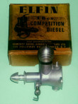
Before There Was Elfin...
The Aerol Engines
by Adrian Duncan
In several earlier articles on this website, we have traced various aspects of the history of the Elfin range of model diesel engines which were manufactured in Liverpool, England by Aerol Engineering between mid 1948 and early 1957. These articles mentioned the Aerol engines which preceded the Elfin range, but few details of those models were presented. Time now to remedy this deficiency!
Indeed, it's actually a matter of some historical importance that we do so. The fact that the Aerol engines have hitherto been very sparsely documented has left many of those who are interested in the early history of British model engines blissfully unaware of the true significance of these designs. We hope that by presenting the Aerol models in the context of their time and place, we may be able to demonstrate that they were in fact highly instrumental in leading British model diesel design from the past into the future. The need to do justice to their manufacturer demands no less. Let's get right to it!
Background
Elsewhere we have recounted the story of Frank Newton Ellis (1909—2003), who was the driving force behind the Aerol Engineering saga. We saw that Aerol Engineering was formed by Frank in late 1946 as an adjunct to a scrap metal business which he and his associates had established shortly after the conclusion of WW2 at premises located on Henry Street, just off Edge Lane in Liverpool 13. Start-up funding for the Aerol Engineering venture was provided by Col. Thomas EH Davies of the well-known Liverpool cotton brokerage firm of Davies, Benachie & Co, who was impressed with the prototype model engines that Frank had developed in his spare time during the previous few years. The Aerol Engineering name was adopted to keep the model engine manufacturing separate from the scrap metal business. Col. Davies took on the role of distributor of the Aerol engines as a sideline to his cotton brokerage business.
The original Aerol production facility was housed in a tin-roofed metal shed in a corner of the scrap-yard! The acquisition of all-new equipment was well beyond the financial capacity of the new venture. Accordingly, the business was started using a very basic inventory of well-used wartime machine tooling obtained from Pratt's in Manchester. This original production equipment included a Herbert capstan lathe, a centre lathe, a drill press and a Delapena honing machine, plus a bench grinder for sharpening tools. All of this equipment had given its best years to the war effort before Aerol ever got hold of it.
By early 1947, Frank Ellis and his associates were ready to commence the development and limited production of a commercial range of model engines. When considering his first commercial design, Frank naturally took note of the popular FROG, Mills, Majesco, Kemp and ED diesels which had already appeared at the time in question. But he was also aware of the Arden spark ignition engines from the USA, having seen a picture of an example, although he apparently never saw any of the internal details of that design. At the time, America was recognized as the world leader in model engine design and production. Frank liked the look of the Arden, feeling that it pointed the way ahead in design terms rather than looking back over its shoulder. How right he proved to be ...!
This led directly to the concept of developing a diesel along Arden lines as opposed to simply repeating the FROG, Mills, Majesco, Kemp or ED pattern. Frank recognized from the outset that the well-equipped American manufacturers with their huge market potential and consequent solid economic base could do better and more cost-effective work on a mass production basis. However, in the context of the far smaller British marketplace, Frank felt that he could design a diesel engine along similar lines that could be made to a sufficiently high standard in commercially-viable numbers with the very limited equipment available. Given the latter constraint, simplicity of construction would clearly be a major design factor in achieving this objective.
The result was Frank's first commercial engine, the 2 cc (0.12 cuin.) Aerol Gremlin diesel, which appeared with little or no fanfare in around June 1947. At this point, some readers may be asking themselves—"Why 2 cc?!?" No doubt a rather odd displacement when viewed from a present-day standpoint, but this is a matter which has to be considered in a late 1940's context as opposed to a 21st century one.
At the time in question, the "magic" displacement of 2.5 cc (0.15 cu. in.) had yet to be adopted by the FAI for International competition, resulting in the competitive use of engines covering a very wide displacement range in the same contest categories. Under these circumstances, no particular displacement really had much of an edge over another. The only issues were what size of model was desired and whether or not a given engine could do the job of flying that model to the standard required. This was particularly true from the standpoint of the sport fliers who then (as now) significantly outnumbered their competition-minded colleagues.
Engines of 2 cc (0.12 cu. in.) displacement or thereabouts were actually quite common in Britain during the period in question. Beginning in early 1947, ED had enjoyed considerable sales and competition success with their 2 cc sideport models, one of which went on to power the 1948 Gold Trophy control-line stunt winner. International Model Aircraft added their FROG 180 diesel to the list in April 1948, while Rawlings also had a 1.8 cc model on the market. Other makers such as Dyne, Majesco and Airstar also offered models of around the 2 cc displacement mark. Aerol themselves continued this trend in mid 1948 when they released the first version of their iconoclastic Elfin 1.8 model which replaced the Aerol designs which we are now discussing. Indeed, as late as April 1949 the K Model Engineering Co were to be found releasing their Falcon 2 cc diesel design, which they followed up later with their Kestrel and Tornado models of similar displacement.
Seen in this mid 1947 context, there was nothing at all extraordinary about Aerol Engineering releasing what was doubtless intended to be a "popular" new model in the 2 cc displacement category. It was only later, when the 2.5 cc limit was formally adopted by the FAI and the British Class 1 (later 1/2 A) displacement limit was set at 1.5 cc, that the attention of British manufacturers became progressively more focused on engines built to the new competition limits, leaving the 2 cc displacement category as something of an orphan lying between competition classes.
Having briefly set the scene for the introduction of the Aerol Gremlin, let's take a close-up look at this very interesting design.
The Aerol Gremlin
Prior to the appearance of the Aerol Gremlin, British model diesel engine design had generally been somewhat stereotypically based upon the classic sideport arrangement which had been established in spark ignition form prior to the onset of WW2. Early British diesels such as the Mills 1.3, the BMP 3.5, the Majesco 2.2, the AMCO .87 Mk I, the ED Mk II, and various Kemp models typified this tendency among British designers of the period to stick with the tried-and-true sideport layout. Even the front rotary valve (FRV) FROG 100 Mk I design, which was based upon the earlier FROG 175 sparker, combined a very "knobbly" old-fashioned look with a marked lack of structural integrity.
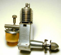
Seen in the context of these "traditional" British designs, the physical appearance of the Aerol Gremlin was little short of revolutionary in a mid 1947 context—nothing remotely like it had ever previously appeared on the British market. It's actually a little difficult today to fully appreciate the extent to which any modeller who had cut his teeth on the established design "formula" would have been totally gob-smacked upon sight of the Gremlin!
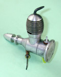
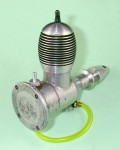
The very sturdy engine featured FRV induction in combination with a sleek, well-coordinated and undeniably futuristic appearance free from all extraneous elements, in sharp contrast to the knobbly look of all the other contemporary British offerings. Put simply, the Gremlin was a far more sophisticated and forward-looking design than any of its British contemporaries—in this respect, it represented a quantum leap forward. Full marks to Frank Ellis for leading the way!
As usual, a few vital statistics are in order at this point. Measured bore and stroke of the long-stroke Gremlin were 0.503" (12.78 mm) and 0.609" (15.47 mm) respectively for a displacement of 1.98 cc (0.121 cuin.). The engine weighed in at a checked 4.94 ounces (140 gm) complete with fuel tubing.
The Gremlin was built up around a pair of very sturdy castings (crankcase and radial tank mount) which were gravity die-cast in piston alloy. In later conversations with family friend Jim Woodside which are summarized elsewhere on this site, Frank Ellis recalled that he made the dies himself. However, the actual castings were produced by a local engineering firm in Liverpool, this being the sole aspect of the engines' production that was contracted out. Frank was very pleased with these early radial-mount cases because they were both strong and extremely resistant to distortion. He had far more trouble with durability and distortion when Aerol Engineering subsequently switched to the less substantial pressure die-cast cases used on the later beam-mount Elfin engines.
In terms of its general layout, the Gremlin clearly reflected Frank Ellis's admiration for the Arden engines. The streamlined radial-mount crankcase with integral main bearing, crankshaft front rotary valve and updraft intake were transferred directly from the Arden models. For reasons of cost, the main bearing ball-races were omitted in favour of a plain bearing with a cast iron sleeve, while the under-slung tank was replaced by a more practical radial tank mount at the rear. However, the overall Arden influence was unmistakeable.
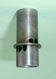
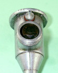
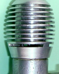
At least, that was true as far as the engine's general external configuration went! Internally, it was a very different story. In particular, the cylinder design departed significantly from that of the Arden. The latter engine featured a screw-in steel cylinder having very thin integrally-machined cooling fins. By contrast, the Gremlin cylinder was an unthreaded steel component of plain tubular form having a location flange part-way down its length. This cylinder was retained by a screw-on alloy cooling jacket of elegant "beehive" form which was internally threaded at its lower end to engage with a male thread formed around the exterior of the upper crankcase casting.
Apart from the different method of construction, the Gremlin's cylinder porting arrangements were very different from those of the Arden. It must be recalled that by his own later admission Frank Ellis never had the opportunity to examine an Arden personally, leaving him without guidance regarding the cylinder porting design. As a result, he had to come up with his own concepts.
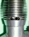
The system actually adopted was a highly unusual form of reverse flow scavenging. The cylinder liner featured a tight group of three transfer ports which were drilled at an upward angle below the cylinder location flange. The exhaust chores were handled by a pair of radially-drilled holes which were placed above the location flange. Most unusually, these latter ports were radially centred at only 60 degrees in a counter-clockwise direction (viewed from above) from the central transfer port location. The movement of incoming transfer gas was thus directed away from the exhaust ports rather than having a velocity component towards them—the fundamental principle of reverse-flow scavenging. The idea behind this is to limit the opportunity for incoming mixture to short-circuit the scavenging process by escaping directly through the exhaust ports. This goal is accomplished by having the transfer gas move more or less directly away from the exhaust ports as it enters the cylinder. The advantage of reverse-flow scavenging is that a baffle is not required to achieve such movement.
The vertical port positioning enforced by the presence of the cylinder location flange placed the transfer ports well below the exhaust ports, necessitating the provision of a sizeable step in the crown of the cast iron piston to create overlap, reduce blowdown period and thus achieve a more appropriate transfer timing. This step was apparently created by hand-filing, implying that at this stage the Aerol workshop still did not have a milling machine available. Indeed, the entire Gremlin design was clearly influenced by the fact that the Aerol company lacked milling capability at this time.
The three grouped transfer ports were fed by a shallow bypass passage formed internally in the crankcase at the front of the cylinder location spigot. This dictated that the transfer ports be located at the front when the engine was assembled. In turn, it required that the piston step be formed at the front of the piston crown. In my example, the piston step is actually positioned a little to the left (viewed from the front) of the engine's axial centre-line. This may be an incidental error arising from the hand-filing operation, or it could be an intentional provision having the objective of directing the incoming transfer gas away from the exhaust ports—in the absence of an opportunity to examine other examples, it's impossible to be certain one way or the other.
The use of a piston having a step formed in a specific orientation eliminated any possibility of following the Arden lead by employing a ball-and-socket small end bearing for the con-rod, since this would have left the piston free to rotate during operation. Instead, the Gremlin used a conventional gudgeon pin small end bearing which maintained the correct alignment of the step.
The need to align the three grouped transfer ports with the front bypass passage in turn dictated the positioning of the two exhaust ports on the left-hand side of the engine (looking forward in the direction of flight) at a 30 degree forward angle—a highly unusual location! The exhaust ports discharged through an oval slot formed by drilling and filing through the alloy cooling jacket at the appropriate elevation above the assembly threads. If you ever encounter an example of the Gremlin with its exhaust ports in any other orientation, you can be sure that it's been incorrectly re-assembled at some point and probably won't run.
All of this presented a significant assembly challenge to the manufacturers of the Gremlin. Oddly enough, no provision was made for the positive radial location of the cylinder liner during assembly. This is surprising given the fact that it is absolutely necessary for the transfer ports to be centrally located at the front in order to conform both to the internal bypass passage and the piston step. A location pin in the crankcase combined with a suitably-positioned slot in the cylinder location flange would have sufficed to ensure the correct alignment, but it wasn't incorporated. This would actually have been a very rational after-market modification for any owner who was experiencing problems with maintaining the correct alignment of the various components.
To make matters even more complicated, it's equally essential that the exhaust slot in the cooling jacket be in perfect alignment with the two exhaust ports when the system is firmly tightened down. Hence, both the cylinder and the cooling jacket have to be in one specific orientation relative to the crankcase and each other when everything is buttoned up tightly.
The correct fitting of the cylinder liner and cooling jacket thus presented a significant assembly challenge. A thin gasket was included between the lower face of the cylinder location flange and the upper crankcase spigot, presumably allowing the adjustment of the system through the judicious use of gaskets of different thicknesses. However, the initial fitting may well have been accomplished in a multi-stage process. First, the engine would have been assembled and tightened down with the cooling jacket completed only to the internal threading stage. The required location of the exhaust port in the cooling jacket would then have been marked, after which the jacket would be removed so that the cooling fins and exhaust port could be added using a threaded mandrel to hold the workpiece.
The engine would then be ready for final assembly with the cylinder liner correctly oriented. The ultimate goal would be to ensure that with the cooling jacket firmly tightened down, the exhaust ports were in alignment with the slot in the cooling jacket and in the correct alignment relative to the crankcase to ensure that the transfer ports corresponded to the bypass passage which fed them. As I know from personal experience, this isn't easy! Once correctly assembled, this engine is definitely best left alone if misalignment issues are to be avoided.
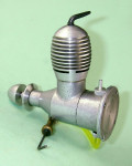
For the most part, the rest of the engine followed completely conventional lines for an FRV diesel of the period. An alloy con-rod engaged with a one-piece steel crankshaft having an un-counterbalanced full-disc crankweb. The prop driver was mounted on a taper formed at the front of the main journal, with the prop being retained by an aluminium alloy spinner nut. The brass needle valve assembly fitted to the updraft venturi was also quite conventional, using a split thimble for tension. The needle was swept back to the left rear at a sharp angle, keeping the fingers well clear of the prop disc and also allowing convenient sidewinder mounting in a control-line application.
The one remaining slightly unusual feature was the tank mount. As with the Arden which inspired a number of key elements of the design, there was no provision for beam mounting. Instead, a separate casting was machined to form a combined radial mount, fuel tank and screw-in backplate in a single component. The front spigot was externally threaded to engage with the female thread at the rear of the crankcase, while the casting was internally machined at the rear to accommodate the fuel. The resulting open rear end of the component was then sealed by a thin aluminium alloy disc which was pressed and swaged into position, very much like the approach used in the FROG engines at the time. Again as with the FROG, removable spigots were threaded into shallow bosses at the top and bottom of the tank to provide for refuelling and fuel pickup. The four holes for radial mounting were oriented in conformity with the alignment of these spigots. FROG influence is very noticeable here.
As with the cylinder, the assembly of this item posed a challenge. The presence of the integrally-cast bosses for the fuel spigots dictated that the tank be oriented in one of two specific locations when fully tightened, such that the spigots were at top and bottom of the tank. This must have involved a degree of trial-and-error fitting, with a combination of selective assembly and variation of backplate gasket thickness presumably being employed. The assembly had to be really tight since starting torque resulting from flicking the engine over would tend to cause the engine to unscrew itself from the backplate. Once running, however, operating torque would tend to keep things nice and tight. I have personally never experienced any problems with one of these engines actually unscrewing itself during starting.
Once the tank was correctly assembled, either spigot could serve as the fuel pickup, with the other used for refuelling. As supplied, the engine could thus be used either upright or inverted, the latter being a very popular mounting orientation at the time of which we are speaking.
Judged against the prevailing standards among British model diesel manufacturers, the resulting engine was unusually compact, tidy and light with a decidedly "futuristic" look about it. The Gremlin was undoubtedly one of the first, if not the very first, British model diesel engines to be designed with a forward view of where model engine design was heading rather than conforming to what had been done previously. Frank Ellis deserves far greater credit for his foresight in this regard than he has hitherto been accorded.
Sharing his recollections many years later with family friend Jim Woodside, Frank stated his opinion that the Gremlin was a "terrific engine"! As part of their product testing program, Frank and his colleagues ran one for a week straight (some 180 hours) on a big tank at 8,000 rpm. Frank claimed that when dismantled after the test it was found to be as good as it had been when first assembled.
The Gremlin caught on immediately despite its somewhat steep asking price of 5 guineas (�5 5s 0d). At the time, model engines were undeniably expensive—the price of the Gremlin was at least equivalent to the weekly before-tax wage of many individuals in cash-starved post-war Britain. However, people would pay such prices for model engines because they were still something of a novelty at the time.
Our ever-patient editor Ron Chernich was kind enough to trawl through his collection of old British modelling magazines for 1947 and 1948. No advertising mention of the Aerol engines was to be found, either as a factory placement or in retail listings. This had us somewhat puzzled until matters became clarified through the emergence of a vital piece of additional evidence to be discussed in detail in the following section.
The Aerol engines never appear to have carried serial numbers—I have yet to encounter one bearing such a number. This initially appeared to preclude any meaningful attempt to come up with a reliable estimate of production figures. However, thanks entirely to the invaluable assistance of our friend and colleague Jim Woodside, we now have a reference which (among other points of clarification) provides an invaluable insight into the issue of production rates at this early stage. This reference is of sufficient importance that we have elected to discuss it in a separate section of this article.
Aerol in the News
On October 30th, 1947, an event occurred which was to have great importance for latter-day model engine historians having an interest in the Aerol engines (all three of us!). This was the appearance in the Liverpool Evening Express newspaper of that date of a short but highly informative article about Frank Ellis and his model engines. It's extremely unusual for a brief reference of this nature to yield so much useful information, so it seems best to deal with the matters arising in turn.
First, the article seems to provide a complete answer to a question which had long bothered us—why are we unable to find any trace of evidence to suggest that the Aerol engines were ever advertised in the British modelling media or even included in the published advertising lists from British retailers, including those in the general vicinity of Liverpool? Moreover, why were they completely ignored by contemporary model engine testers and commentators, despite their revolutionary design? The article clarifies this completely—all of the engines produced were destined for export, at least as of the date of the article! Hence it is in the modelling media (if any) of the countries to which exports were reportedly sent (including Australia, Canada, New Zealand, Africa and India if the article is correct) that we should look for any promotional efforts. We leave this as a challenge for others to take up!
It seems clear from this that Frank and his associates were taking full advantage of Government incentives then being offered to British industry to encourage the export of their production to overseas markets. The end of WW2 had left Britain with a serious foreign currency deficit as well as nursing a massive National Debt. The Government of the day quite logically saw the export of British goods as being a positive step towards the redressing of this situation, launching a major export drive under which a range of incentives were offered to companies who were prepared to commit to the export of the bulk of their production. Frank and his colleagues appear to have taken full advantage of this situation.
Indeed, the major focus of the article was on the apparent success of the Aerol manufacturers in generating sales in export markets. Presumably the International business connections which Col. Davies had doubtless developed through his participation in the world-wide cotton industry were of material assistance in this regard.
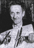
However, the engines themselves did draw their share of attention. The models mentioned in the article were the Gremlin and a previously-unrecognized Aerol design, the Elf of 0.8 cc displacement, which would appear to have been in effect a scaled-down Gremlin. Frank was pictured holding an example of each of these models. The selling price of the Gremlin was quoted as 5 guineas (�5 5s 0d, or �5.25 in "modern" money). The article stated that the Elf was then set to join the Gremlin in production. However, the complete absence of any known examples or any further mention of the 0.8 cc Elf strongly suggests that production of such a model never commenced.
That said, there may be far more to the story than this! Jim Woodside set the ball rolling by suggesting the possible significance of the name Elf—this seemingly still-born project may in fact represent the initial inspiration for the name "Elfin"! This thought led me to a closer perusal of the photograph of Frank and the two engines which accompanied the article. It became immediately clear that, whatever it actually was, the illustrated "Elf" was certainly not a 0.8 cc model! In the photograph, it appears to be very little smaller than the accompanying "Gremlin". Put an Elfin 1.8 alongside a Gremlin, and the size relationship appears identical to that seen in the photo. Moreover, despite the poor quality of the greatly enlarged image, a number of points of design similarity between the "Elf" and the later Elfin 1.8 are readily apparent.
This leads directly to the almost inescapable conclusion that the true displacement of the "Elf" was 1.8 cc, not 0.8 cc as reported, and that the engine that Frank was holding for the photo was in fact an early prototype of what was to become the Elfin 1.8, complete with a partial rendering of the Elfin name! This seems far more likely than the notion of Frank developing a new 0.8 cc model to the prototype stage and then never producing it. The quoted displacement presumably arose through a mis-communication between Frank and the reporter.
The probability that this interpretation is correct is greatly reinforced by the fact that at no point during his recorded chats with Jim Woodside did Frank ever refer to a 0.8 cc model. Unfortunately, there's no longer anyone to whom we can turn for authoritative first-hand confirmation. We have to confine ourselves to noting the possibility that the genesis of the Elfin range dates from considerably earlier than we had previously believed.
As if this wasn't enough, the article also clarified both the staffing levels and the production rates at Aerol Engineering as of the publication date. The article named one Harold Leahy as Frank's partner in the business at this time, going on to state that the partners were then completing around 20 engines weekly with the assistance of two other employees. It's clear from the claims regarding export sales up to that point that the Gremlin must have been in production for some time as of the date of the article, presumably at the same 20 engine per week rate or thereabouts. We probably wouldn't be far wrong in suggesting that for the export claims to be factually-based, the production of the engine must have commenced in around June 1947. If this is the case, some 400 or so engines would likely have been completed as of late October 1947. This was probably very close to the final figure, since indications are that the Gremlin was in fact replaced soon thereafter by the Hurricane, of which more below in its place.
The cited staffing levels may seem very small for such a venture, but such low staffing levels were by no means uncommon during this period—the contemporary Kemp Engines business of Gravesend, Kent is known to have been very similarly equipped to Aerol and to have operated initially with three full-time employees plus one part-timer. In light of this comparison, it's interesting to note that information derived from serial numbers implies that the 3-1/2 man Kemp operation managed to produce around 150 engines per month as compared to the 80 or so managed by Aerol.
A ready explanation for this apparent discrepancy is to be found in the realization that model engineering manufacture at Aerol was not a full-time preoccupation for those involved—Frank and his associates were also running their scrap metal business at the same time. This would have limited the amount of time that they could devote to the manufacture of model engines. By contrast, the sole activity at Kemp Engines was model engine manufacture.
Frank was later to recall that the maximum number of staff ever employed by Aerol Engineering was around seven, this being confined to a period when the much later Elfin 1.49 PB was selling as fast as they could make it and production figures occasionally reached as high as 200 engines per week.
Although the absence of any authoritative references has rendered it impossible to establish definite dates, all indications suggest that the Gremlin remained in production for no more than 5 months or so before being replaced in around November 1947 by the Hurricane which will be covered in a later section of this article. If this is correct (and we admit that it is at best an educated guess at this point), then total production of the Gremlin was likely around 400 units. This relatively low figure is entirely consistent with the engine's extreme rarity today.
The Aerol Gremlin on Test
As noted earlier, neither of the models produced and sold under the Aerol banner was ever the subject of a published test in the modelling media. This being the case, we'll just have to fill that omission ourselves!
It's always valuable to have a basis for comparing a given engine's performance to that of its major competition. In this instance, I had a reliable set of previous measurements for perhaps the most popular 2 cc unit in Britain at the time—the 1947 small-bypass ED Mk II. At the time when the Gremlin appeared, the Mk II was ED's sole 2 cc model—the more powerful Comp Special with its sub-piston induction and larger bypass had yet to appear. The comparison thus seems entirely fair. As a bonus, I also had figures for the contemporary Majesco "22" model of 2.2 cc displacement.
In addition to my existing test figures for the Mk II and the Majesco, I actually had some previous numbers for the Aerol Hurricane which will be discussed in the following section of this article. This gave me a basis for selecting an appropriate array of test props which should yield the required comparative performance data for the Gremlin. Armed with these plus some suitable fuel, I headed out to the test area.
The Gremlin proved to be a very easy starter indeed provided a small prime was first administered. This is a normal characteristic of updraft-intake engines in an upright mounting, since any fuel which reaches the intake from the fuel line simply drips out of the engine rather than being absorbed. However, a light prime was the only necessary prerequisite to an instant start—the engine almost invariably fired up with one or two flicks, picking up right away on the fuel line. I found that a prime administered with the exhaust ports closed gave the best results.
The contra piston in this example proved to be rather more tightly fitted than ideal, but the compression setting remained fully adjustable at all times despite this. Needle response was excellent—very positive without being overly sensitive. Optimum settings were thus easy to establish. Running qualities were first class, with no trace of misfiring and a very steady speed being held on any given prop.
One noteworthy characteristic was the engine's outstanding ability to "throttle down" through a combination of compression and needle adjustments. Most unusually, the motor simply slowed down when adjusted in this manner, with none of the usual "burp-burp" behaviour for which diesels tend to be known. It behaved far more like a glow-plug motor than a diesel in this respect. Power delivery remained very constant, albeit at a significantly lower level. This would have been a great asset for trimming and the like.
Prior to the commencement of the tests, I was a bit worried about the possibility of the cooling jacket "doing a Sparey" on me by unscrewing during operation. Given the alignment issues described earlier, this would have created serious difficulties in the field! However, I needn't have worried—everything stayed nice and tight for the entire duration of a fairly arduous test.
I was quite frankly rather astonished at the level of performance exhibited by this engine. I had been expecting a competent but not outstanding performance, but what I actually got was a truly excellent set of figures by the standards of 1947. The numbers recorded on test were as follows, together with the derived power curve:
| Prop | RPM | BHP |
|---|---|---|
| 9x6 Taipan | 7,600 | 0.110 |
| 9x6 APC | 7,800 | 0.114 |
| 8x6 Tornado | 8,400 | 0.123 |
| 9x4 APC | 8,700 | 0.128 |
| 8x6 Taipan | 8,800 | 0.131 |
| 8x6 APC | 9,100 | 0.132 |
| 8-1/4 x4 APC | 9,200 | 0.131 |
| 7-1/4 x6 APC | 9,400 | 0.127 |
| 8x4 APC | 10,000 | 0.116 |
The power curve (below) derived from these figures implies a peak output of around 0.133 BHP @ 9,000 rpm—an outstanding performance as of 1947, and one which was unmatched by any competing British 2 cc diesel of my present acquaintance. My earlier test of the small-bypass ED Mk II indicated a peak output of around 0.086 BHP @ 7,000 rpm, while the 2.2 cc Majesco "22" proved on test to develop only 0.096 BHP at a little less than 6,000 rpm. In performance terms, it was no contest—the Gremlin simply buried the contemporary opposition, as well as being significantly lighter and more compact.
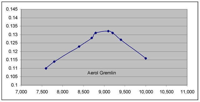
Aerol - Power Curve
How did Frank Ellis characterize the Gremlin? A "...terrific engine..." ? Seems entirely appropriate to me!
The Aerol Hurricane
Although the Gremlin embodied a number of features which were to be enshrined in the British model engine design genre for many years to come, it still fell somewhat short of Frank's expectations in a number or areas, particularly given its Arden heritage. Since the Gremlin's major design departure from the Arden pattern (apart from the ball-race shaft and the ignition system) was its cylinder porting configuration, it was inevitable that this feature would soon come under scrutiny by its designer. There were also a number of production difficulties which merited correction.
The Arden featured full 360 degree radial porting, in contrast to the Gremlin's far more restrictive form of reverse-flow scavenging described above. Apart from its more restrictive nature, the Gremlin's porting also imposed the previously-noted assembly difficulties, since the cylinder and cooling jacket not only had to be correctly aligned with one another but also had to be positioned relative to the crankcase so as to place the transfer ports in their correct location at the front. The piston crown also had to be stepped to create the desired transfer timing.
Accordingly, a new cylinder design was developed which featured a form of radial porting that was far closer to the Arden set-up. There were three sawn exhaust slots equally spaced around the cylinder circumference. Directly beneath each of these ports was an internally-formed transfer flute which terminated just below the respective exhaust port. Since no overlap was possible with this arrangement, a relatively long blowdown period was unavoidable. However, the blowdown period was minimized by the fact that that the exhaust ports were relatively shallow by comparison with the round holes of the former Gremlin component, thus minimizing the necessary delay in the opening of the transfer ports.
Moreover, the shallow exhaust ports became fully open much faster in terms of degrees of crank angle as the piston descended. They also had a larger total area than those of the Gremlin when fully open. The combination of a larger exhaust area with more rapid complete opening would be expected to assist the clearance of exhaust gasses quite materially. The scavenging was still of the reverse-flow variety, but this was now achieved more conventionally by directing the incoming gas towards the axial centre of the cylinder and thence upwards beneath the escape path of the exhaust gasses.
Naturally the re-design of the cylinder required a matching re-configuration of the aluminium alloy cooling jacket. The basic form of the jacket was unchanged, but it now had thee milled slots at exhaust port level to permit the egress of exhaust gasses from the cylinder (implying incidentally that by now the Aerol company had acquired milling capability). The size of the ports was such as to require that the jacket be aligned so that the cylinder ports corresponded to the slots in the cooling jacket when things were screwed down hard.
Consequently, the former assembly issues were not completely eliminated—the tightened-down alignment of the jacket relative to the cylinder still had to be correctly established. However, the revised bypass arrangements relieved the makers of the need to ensure that both the jacket and the cylinder were correctly aligned with the crankcase as well as with each other—the engine would run in any alignment of the combined cylinder/jacket assembly. This eliminated one significant element of the former assembly problem, in particular the need for selective matching of parts. A further manufacturing simplification was the elimination of the need to create a step in the piston crown.
The revised model which was fitted with this re-designed cylinder and jacket was called the Aerol Hurricane. Although the dates are not certain, it appears to have been introduced in around November 1947 following some five months of Gremlin production.
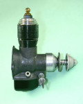
Apart from the cylinder design, the Hurricane was little changed from its Gremlin forebear. Bore and stroke were unaltered at 0.503" (12.78 mm) and 0.609" (15.47 mm) respectively for a displacement of 1.98 cc (0.121 cuin.). Weight too was very little changed at 4.83 ounces (137 gm). The tank arrangements remained the same, along with the attendant assembly difficulties.
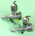
A few detail differences were apparent. The design of the prop driver and spinner nut combination was changed slightly. In addition, the revised cooling jacket had fewer cooling fins. Finally, the angle at which the needle valve was swept back was substantially reduced. But none of these points had any functional effect on performance—in that respect, the difference between the two models was confined to the cylinder design.
It's probable that production levels for the Hurricane were little changed from those achieved with the Gremlin since the Aerol company doesn't appear to have commenced the construction of the substantial brick factory which replaced their original metal shed until after the Elfin engines were introduced. The Hurricane may possibly have remained in production for a month or so longer than the Gremlin, but this is not certain. Regardless, the implication is that at the very most some 500 examples may have been made in total. The true number may well have been somewhat less. What is indisputable is that surviving examples of the Hurricane are almost as rare as those of the Gremlin.
The Aerol Hurricane on Test
As in the case of the Gremlin, we have no contemporary published test report to which reference may be made. Accordingly, it's down to us to put the Hurricane through its paces!
By the time the Hurricane made its appearance, ED had come out with the improved Comp Special version of their established 2 cc design, now featuring sub-piston induction in addition to a significantly larger bypass passage. It thus seemed reasonable to compare the performance of the Hurricane with that of the Comp Special for the purposes of this review. Since I already had a reliable set of test figures for the Comp Special, there was no need to repeat that exercise.
The Hurricane had accompanied its Gremlin partner on my trip to the testing site, so as soon as the Gremlin test was done the Hurricane replaced it on the test block. The same props and fuel were used, making a direct comparison completely valid.
In terms of its handling and running characteristics, the Hurricane proved to be more or less a clone of its partner, starting with unfailing ease on a small prime and running perfectly throughout. This didn't surprise me—what did puzzle me somewhat was the fact that the Hurricane fell a little short of matching the performance of the Gremlin! Frankly, I had been expecting the reverse to be the case. The figures obtained on test were as follows, along with the derived power curve:
| Prop | RPM | BHP |
|---|---|---|
| 9x6 Taipan | 7,100 | 0.090 |
| 9x6 APC | 7,400 | 0.098 |
| 8x6 Tornado | 8,200 | 0.115 |
| 9x4 APC | 8,500 | 0.119 |
| 8x6 Taipan | 8,600 | 0.122 |
| 8x6 APC | 8,800 | 0.119 |
| 8-1/4 x4 APC | 8,900 | 0.118 |
| 7-1/4 x6 APC | 9,100 | 0.115 |
| 8x4 APC | 9,800 | 0.109 |
The data presented above implies a peak output of around 0.122 BHP @ 8,600 rpm, slightly down on the 0.133 BHP @ 9,000 rpm recorded for the Gremlin. Since the two engines have completely different scavenging arrangements, there's no reason to expect them to perform at the same level, but it does seem a bit odd that the later design appears to have fallen slightly short of its predecessor in performance terms. That said, the difference in performance is sufficiently small that in practical terms the two perform at very similar levels—one would not notice much difference in the field.
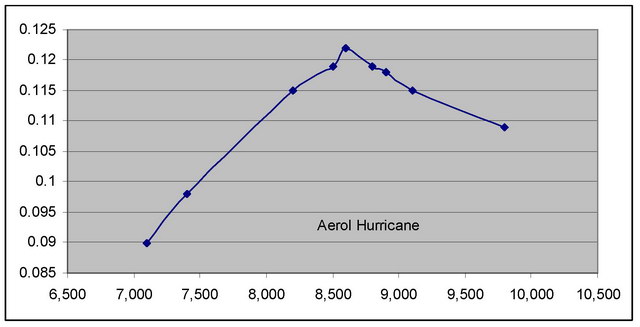
Hurricane - Power Curve
Even so, the Hurricane showed that it remained abreast of the improved competition represented by the ED Comp Special. My earlier test of that model indicated a peak output of around 0.121 BHP @ 8,200 rpm. This of course represents a very substantial increase over the earlier Mk II. However, the Hurricane could match the Comp Special prop for prop while being considerably lighter and more compact into the bargain.
One point worth noting is the fact that the Hurricane lacked the outstanding ability of the Gremlin to run smoothly at reduced compression settings and richer mixtures. It exhibited the usual "burp-burp" behaviour associated with diesels when throttled back in this way. On that basis, it would have been slightly less user-friendly in a trimming context. This must of course be down to the significantly revised porting arrangements.
Enter Elfin
Although the Hurricane represented a worthy attempt to deal with some of the assembly challenges associated with the Gremlin, Frank Ellis was clearly still not satisfied. A number of manufacturing issues remained unaddressed, while the Hurricane's evident failure to raise the performance bar must surely have rankled.
We previously noted the possibility that as far back as October 1947 Frank may well have produced a prototype of an entirely new design to replace the Aerol models, although developing the tooling and arranging for the required castings for this model would of course have required both time and a capacity to invest further funds, luxuries which Frank clearly didn't have in abundance.
However, as 1948 drew on, it must have become increasingly apparent that a change was necessary. Apart from the fact that other manufacturers were catching up to the Aerol designs in performance terms, it's highly likely that a contributing factor here was the ongoing assembly challenge posed both by the Hurricane's cylinder design and tank mount assembly. There also appears to have been a desire to shave some more weight and bulk off the engine, thus enhancing one of the major competitive advantages enjoyed by Frank's designs.
The result was the mid 1948 appearance of an engine that was destined to become the stuff of legend—the original radial-mount Elfin 1.8. In his discussion many years later with Jim Woodside, Frank was to recall that following its introduction he took one of the new Elfin 1.8 cc models to a major contest at Leighton Buzzard, strictly to promote the engine. This appears to have been Frank's first significant move towards domestic promotion of his engines—previously, export sales had evidently been the focus. It appears that Government pressure upon Aerol to export the bulk of their production had eased somewhat at this point in time, or perhaps they had met their target quota and had excess production capacity available to serve the domestic market. Whatever the reason, all future Aerol products were marketed quite aggressively in Britain as well as in overseas markets.
Frank recalled that on first starting the engine up he immediately attracted a large crowd—that famous Elfin "crackle", no doubt! One of the individuals in the crowd was none other than Henry J Nicholls, who told Frank on the spot that he would take as many as Frank could supply! Nicholls in fact appears to replaced Davies, Benachie & Co as the major domestic distributor of the Elfin range—certainly, the Elfin box labels from this early period identified Nicholls in this capacity. It's worth noting in passing, however, that Davies, Benachie retained a connection with Aerol despite Nicholls' intervention, since their name continued to appear on Elfin advertisements as the export concessionaires for the range.
The first advertising reference to this engine that Ron Chernich was able to find was its appearance in the Henry J Nicholls placement in the August 1948 issue of Aeromodeller, with Aerol Engineering beginning for the first time to place their own national advertisements soon thereafter. However it seems almost certain that the engine actually appeared a few months earlier than that, likely in around June 1948.
This implies that the manufacture of the Aerol Hurricane had ceased as of May 1948 after some 5 or perhaps 6 months in production. As noted earlier, it's highly unlikely that total production of the Hurricane exceeded the 500 unit mark—in fact, it way well have been somewhat less. The engine is certainly elusive today.
Although the manufacturer of the new 1.8 was still Aerol Engineering, this was the first model to be sold under the soon-to-be-famous Elfin trade-name. No more engines were destined to be sold as Aerol products—that line ended with the Hurricane. Anecdotally, the Elfin name arose because Frank was quite taken by the result of combining a pair of names—Frank's family name of Ellis and the family name of one of his associates, a certain Mr. Finn.
The slightly reduced displacement of the Elfin 1.8 was achieved through a reduction in the stroke from 0.609" (15.47 mm) to 0.562" (14.27 mm). The bore remained essentially unchanged at 0.505" (12.83 mm), yielding a marginally reduced displacement of 1.84 cc (0.112 cuin.) as opposed to the Hurricane's figure of 1.98 cc (0.121 cuin.). The major consequence of this change was that the 1.8 was considerably less under-square than the Hurricane, reflecting an emerging trend in model diesel design as peaking speeds went up.
The shorter stroke also resulted in a considerably more compact and hence lighter unit—the 1.8 weighed only 3.91 ounces (111 gm) as opposed to the 4.83 ounces (137 gm) of the Hurricane. These figures make it appear likely that weight reduction was a major driving force behind the changes between the two models.
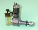
In very broad terms the Elfin 1.8 showed clear evidence of its Hurricane ancestry, including the ongoing influence of the Arden engines. The revised cylinder featured exactly the same porting arrangements as on the Hurricane apart from the use of four ports as opposed to the former three. In addition, the cylinder was externally threaded above the port belt to allow the use of a screw-on cooling jacket which did not obscure the exhausts. Below the port belt, the cylinder was externally threaded to match a female thread formed inside the upper crankcase casting. This completely eliminated the assembly issues which had been inherent in the Hurricane design—the engine would work perfectly well regardless of where the components ended up when tightened down. No doubt this too was a major design objective.
The tank arrangements too were very different. The 1.8 used a conventional screw-in backplate together with an open-backed conical Arden-style radial mount which was cast in unit with the crankcase. The free-flight version had provision for a plastic tube tank (for which end plugs with spigots were provided), while the control-line version had no tank provisions at all. Again, this eliminated the selective assembly requirement imposed by the design of the Hurricane.
Overall, the design of the Elfin 1.8 was functionally very similar to that of the Hurricane apart from the use of four ports in place of the former three. In addition to the slight reduction in displacement, the main effect of the changes was the elimination of some weight and bulk along with the improvement of the transfer arrangements through the addition of an extra transfer port. Perhaps equally importantly, the revisions eliminated several assembly challenges. A very clear case of a capable designer learning from experience.
A test of an example of the Elfin 1.8 undertaken on the same day as the previously-documented tests of the Aerol models demonstrated in no uncertain terms that the Elfin represented a very clear step forward in performance terms. The figures obtained were as follows, together with the derived power curve:
| Prop | RPM | BHP |
|---|---|---|
| 9x6 Taipan | 7,200 | 0.094 |
| 9x6 APC | 7,800 | 0.116 |
| 8x6 Tornado | 9,000 | 0.152 |
| 9x4 APC | 9,200 | 0.155 |
| 8x6 Taipan | 9,400 | 0.159 |
| 8x6 APC | 9,600 | 0.155 |
| 8-1/4 x4 APC | 9,700 | 0.153 |
| 7-1/4 x6 APC | 9,900 | 0.150 |
| 8x4 APC | 10,800 | 0.136 |
The implied peak output of 0.160 BHP @ 9,300 rpm puts the 1.8 streets ahead of both the Hurricane and the Comp Special on a performance basis, while in terms of its lightness and compactness it was simply no contest. A very significant achievement on the part of Frank Ellis! It's noteworthy that the specific output of 0.087 BHP/cc is very little inferior to the figure of 0.097 BHP/cc reported by Peter Chinn (and subsequently confirmed by my own testing) for the later Elfin 2.49 PB radial mount model.
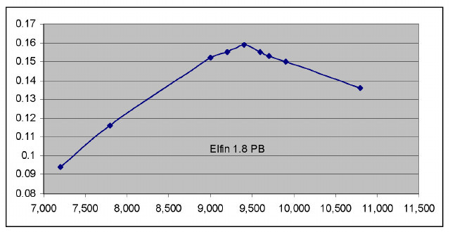
Elfin 1.8 PB - Power Curve
It's also worth mentioning in passing that the above figure for the engine's peak output significantly exceeds that obtained by Lawrence Sparey in his July 1949 test of the Elfin 1.8. Sparey reported figures of 0.114 BHP @ 12,100 rpm, results which are in no way supported by my own testing reported above. It appears that my example developed significantly greater torque than that tested by Sparey.
The Elfin 1.8 was the first of a series of engines to be released under the Elfin banner. The marque was destined to enjoy considerable sales and competition success, although as time went by it became increasingly bedevilled by quality control problems arising from the company's enforced dependence upon the clapped-out wartime machinery which they could not afford to replace. In the end, this proved to be the company's downfall—by early 1957 the quality control issues had reached the point where the manufacture of the Elfin engines by Aerol Engineering had to be suspended and the company wound up.
But that's another story, which we have already recounted in detail elsewhere on this website...
Conclusion
Neither the Gremlin nor the Hurricane are commonly encountered today. As a result, when they do appear on eBay or elsewhere they tend to sell for relatively high prices, especially if in complete and original condition.
In large part, the rarity of these engines is doubtless due to the fact that not that many were manufactured. However, paradoxically it may also reflect the fact that both models were very serviceable and durable engines which would have served their owners well. This may have led to them being simply run into the ground before being discarded when worn out. It's the good engines that get the air time and take any lumps that are going! Any limited-production vintage engine that shows up in significant numbers in near-mint condition probably isn't much of an engine ...!
All of this having been said, the Aerol engines are highly significant in being the first British model engine designs to make a clean break with the past and steer British model diesel manufacturers towards the design path of the future. Their designer Frank Ellis deserves far greater credit for this than he has hitherto been accorded. The Aerol designs were also the direct precursors of one of the most influential British model engine ranges of the middle 20th century—the Elfin marque. Consequently, they richly deserve both our remembrance and our respect.
We hope that you've enjoyed our look at these highly influential motors! As always, if anyone out there knows more or can set us straight at any point, please get in touch! All contributions gratefully and openly acknowledged...


