Building the 1939 M&M .29 Ignition Engine
Created: September 10, 1999
Last update: Dec 21, 2006
The M&M was marketed around 1939 and was extremely innovative for its day, or any other day for that matter. For this reason, it was chosen as the first Motor Boys project. My example was completed in January 1999 after a rather long gestation period. The following few pictures and words should give you some idea of the project.
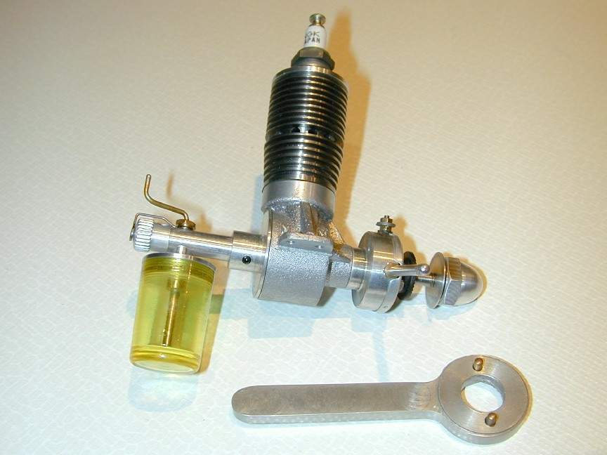
The M&M features two pressure actuated valves: one for in the backplate for induction and another in the crown of the piston for transfer. The ignition point mechanism (the so called "timer") is a totally enclosed design to prevent dirt contamination which was a problem with early model engines. The fuel regulation mechanism uses one tube rotataing within another. The inner carries a flat that permits fuel to flow through a hole into the induction tube. The top of this inner tube is bent into a crank shape and sealed on the outer end. Thus, rotating the crank in either direction from where the flat faces the hole will regulate (restrict) the fuel flow. The whole fuel system can be rotated and locked in relation to the engine, permitting the cylinder and tank to be arranged in any orientation desired. The rear of the induction tube is closed of by a rotating choke cap. As I said, a very innovative design, for any era!
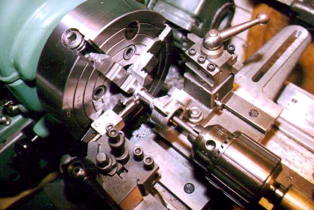
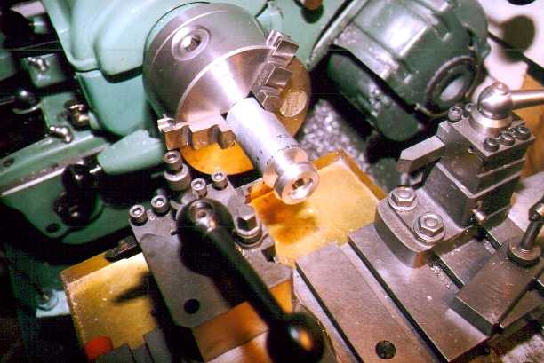
As usual, machining the sand cast aluminum crankcase begins with the crankshaft cavity and bore. To do this, the casting is set up in the 4 jaw independant chuck so that the rear of the casting is centred. But before doing this, the centre of the cylinder seat must be established so the correct distance from vertical centre line to backplate seating face can be established. The shaft bore can then be pilot drilled and the cavity bored out and threaded for the backplate. After reaming the crankshaft bore for the bronze crankshaft bushing, the crankshaft is parted off from the maching stub as seen in the next photograph. To do this, a short mandrel mounted in the tailstock is brought up into the case to catch it as the parting off tool breaks through. I've had one crankcase destroyed as it bounced off the cross slide and fell between apron and rotating chuck. Not a pritty sight. For the curious, the slotted arm protruding from the rear of the cross slide on my Myford Super 7B is a taper turning attachment that stays permanently attached, giving me a bit more horizontal space to have things fall down from.
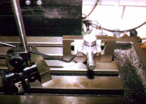
 Next, the crankcase is mounted on an angle plate so it can be attached to a lathe faceplate to bore the cylinder mount at precisely 90 degrees to the crankshaft axis. The next photo shows preparation for this operation using a scribing block to establish equal hights of the mounting lugs above a horizontal surface (the mill table in this case). The case is held with a bolt accurately centred and measured so the correct height of the cylinder seating face from the crankshaft axis can be established.
Note the thin card between the angle plate and the crankcase to protect the face and give a non-slip mount. Old business cards are ideal for this. The business card is a wonderfull workshop aid. Fortunately, they seem to be in plentifull supply these days owing to the frequency of changes in work status of my friends and myself!
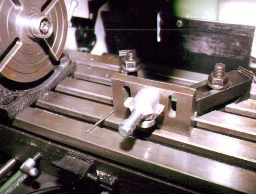
 In the next shot, the angle plate has been returned to the mill table after the vertical boring operations are completed to mill out the clearance slot for the connecting rod. This has been done and the case rotated by 180 degrees to machine the bottom of the mounting lugs and drill the mounting holes.
 The crankcase is now essentially complete and work moves onto the parts to be made from bar stock. These are the backplate (incorporating the induction valve cavity as seen in the photograph), the timer body, tank top and the cylinder head. All straight forward turning jobs, although work holding for second operations on the head and backplate can be challanging.
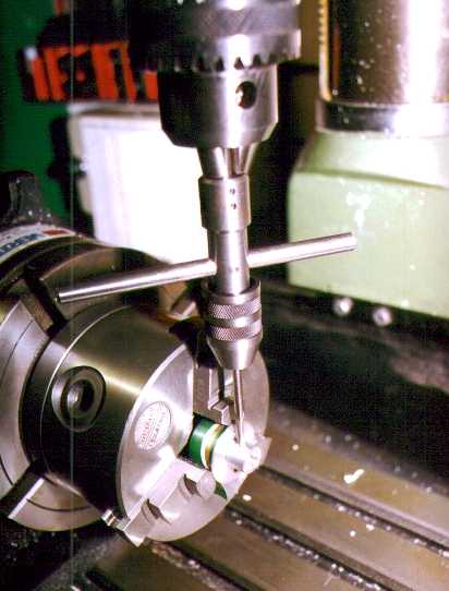
 Being able to transfer the 3 jaw chuck between the lathe spindle and rotary table on the mill is a terrific productivity aid! Here, the backplate is drilled and tapped for the screw that will lock the inlet tube. I try to do drilling and tapping at the same time, using the quill to guide the tap. In the following shot, the tap wrench is guided by a short stub in the drill chuck that permits free vertical and turning movement. The green material is aluminum drink can stock which makes good protective packing when something a little more substantial than business cards is required.
 Normally at this stage, a model engine project is just starting, but in my case, it was nearly over. You see, the group of which I'm privileged to me a member makes engines my mail - both Internet email and regular old snail mail. Having reached this stage, I needed only to fit the parts I'd made together with those made by others in our team and there was a pristine M&M, circa 1939! I can't thank these guys enough for the fine parts they contributed to my engine. They are:
-
David Owen, NSW, OZ (absolutely beautiful cylinder and piston work)
- Don McClusky Austin, TX (fully fabricated and perfectly aligned crankshaft and con rod)
- Roger Schroeder, Overland Park, KS (all castings with crafty lettering and the project Ram Rod)
- Don McClusky Austin, TX (fully fabricated and perfectly aligned crankshaft and con rod)
-
Bert Striegler, Rochelle TX (spun timer cover, "Stanley" fuel tank and other fiddley bits and pieces)
Great job, guys!


This page designed to look best when using anything but IE!
Please submit all questions and comments to
[email protected]